

Plug replacement device for vacuum use of tank and working method of plug replacement device
A technology for plugs and tanks, which is applied in the field of plug replacement devices for vacuum tanks, which can solve the problems of inconvenient replacement, reduced working reliability, and difficulty in observing the use status, etc., and achieves the effect of convenient replacement and convenient observation
- Summary
- Abstract
- Description
- Claims
- Application Information
AI Technical Summary
Problems solved by technology
Method used
Image


Examples
Embodiment Construction
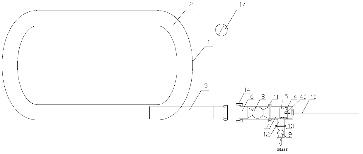
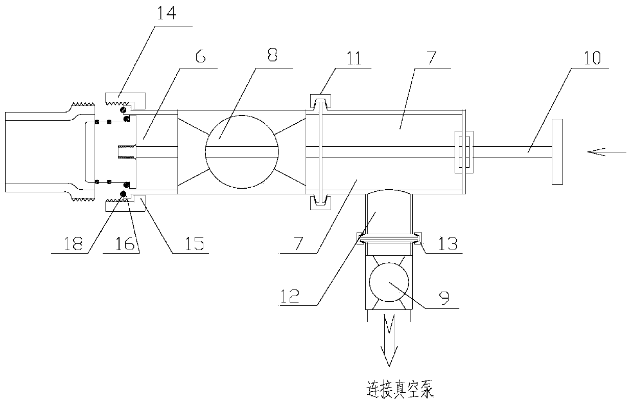
[0035] The present invention as Figure 1-2 As shown, the outer wall of the tank body 1 is provided with an interlayer 2, and the interlayer is connected with an auxiliary pipe 3, and the auxiliary pipe is provided with a plug 4, and the plug is provided with a sealing ring 5;
[0036] It also includes valve body one 6, valve body two 7, vacuum ball valve one 8, vacuum ball valve two 9 and valve stem 10, the two ends of the valve body one are provided with openings, and one end of the valve body one is detachable from the auxiliary pipe Connection, the other end is fixedly connected with the vacuum ball valve;
[0037] One end of the valve body 2 facing the vacuum ball valve 1 is provided with an opening, the vacuum ball valve 1 is connected to the valve body 2 through a clamp 11, and the valve stem is connected to the end of the valve body 2 away from the vacuum ball valve 1. The valve stem is movably connected in the valve body 2, the vacuum ball valve 1 and the valve body ...
PUM
 Abstract
Description
Claims
Application Information