Supercharge Your Innovation With Domain-Expert AI Agents!

Positioning and cutting device for cylindrical shaft parts

A technology for positioning cutting and cylindrical shafts, applied in positioning devices, metal processing machinery parts, manufacturing tools, etc., can solve the problems of inability to position cylindrical parts, difficult cutting accuracy, and easy rotation, etc., to achieve good practicability, Strong applicability and the effect of ensuring cutting efficiency

Active Publication Date: 2021-03-23
刘安胜
View PDF8 Cites 0 Cited by
  • Summary
  • Abstract
  • Description
  • Claims
  • Application Information

AI Technical Summary

Problems solved by technology

[0002] In the field of motors, some cylindrical shaft parts are often seen, which are mainly used to support transmission parts, transmission torque and bear loads. Generally, they can be divided into optical shafts, stepped shafts and special-shaped shafts. At the same time, they are mostly metal or Plastic material, cutting is sometimes required during the processing of such cylindrical shaft parts. Although there are many types of cutting devices on the market, due to the special shape of cylindrical shaft parts, traditional cutting devices cannot be effective. The positioning operation of the cylindrical parts is easy to rotate or shift during cutting, so it is difficult to effectively ensure the cutting accuracy, so it is necessary to set up a special cutting device for processing

Method used


Image

  • Positioning and cutting device for cylindrical shaft parts

Examples


Embodiment 1)

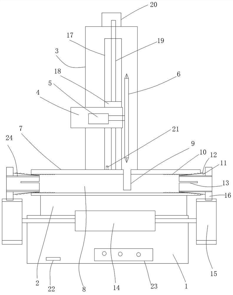
[0017] figure 1 A specific embodiment of the present invention is shown in which figure 1 A structural diagram of the invention.

[0018] see figure 1 , A positioning cutting device of a cylindrical shaft, including a base 1, a cutting platform 2 disposed on the base, a bracket 3 is provided in the middle of the base, and a cutting seat 4 is provided on the bracket 4 In the cutting seat, a cutting motor 5 is provided, and a cutting tool 6 is fixed on the spindle of the cutting motor, and a positioning seat 7 is provided on the cutting platform, a circular pass is provided on the positioning. The hole 8 is fixed to the cutting groove 9 at the top center of the positioning seat, and the cutting groove is perpendicular to the circular vias, and the cutting groove is disposed at a cutting tool, at the circular vias Both ends of the inner wall are fixed, and the internal thread 10 is respectively provided with a circular ring lock block 11, and one end surface of the circular ring loc...


PUM


Abstract

The invention discloses positioning cutting equipment of cylindrical shaft parts. The positioning cutting equipment of the cylindrical shaft parts comprises a bottom seat and a cutting platform arranged on the bottom seat, a support is arranged in the middle of the side surface of the bottom seat, a cutting seat is arranged on the support, a cutting motor is arranged on the cutting seat, a cuttingtool is fixed to a main shaft of the cutting motor, a positioning seat is arranged on the cutting platform, the positioning seat is provided with a circular through hole, a cutting groove is fixedlyformed in the center of the top of the positioning seat, the cutting groove is perpendicular to the circular through hole, the cutting groove is arranged under the cutting tool, inner threads are respectively fixed to the two ends of the inner wall of the circular through hole, ring-shaped position locking blocks are respectively arranged at the two ends of the circular through hole, the outer surfaces of one ends of the ring-shaped position locking blocks are inclined surfaces, and outer threads matched with the inner threads are arranged on the inclined surfaces. According to the positioningcutting equipment of the cylindrical shaft parts, the structure is reasonably arranged, the cylindrical shaft parts can be effectively and quickly clamped and positioned, the cutting precision and the cutting efficiency can be effectively guaranteed, and applicability and practicability are good.

Description

Technical field [0001] The present invention belongs to the technical field of component processing equipment, and more particularly to a positioning cutting device of a cylindrical shaft. Background technique [0002] In the field of motor, some cylindrical axis components are often seen, which is mainly used to support the transmission parts, drive torque, and withstand loads, generally divided into optical axes, step shafts, and shaped shafts, while they are most metal or Plastic material, during the processing of such cylindrical shaft parts, the cutting process is sometimes required, although there are many types of cutting devices on the market, but due to the shape of the cylindrical shaft part, the cutting devices of the conventional technique cannot be effective. The cylindrical part is positioned, thereby easily rotating or shifting at the time of cutting, so that it is difficult to effectively ensure the precision of the cut, so it is necessary to provide a special cut...

Claims


Application Information

Patent Timeline
Patent Type & Authority Patents(China)
IPC IPC(8): B26D7/02B23Q3/06
CPCB23Q3/064B26D7/02B26D2007/013
Inventor 刘安胜
Owner 刘安胜
Features
  • R&D
  • Intellectual Property
  • Life Sciences
  • Materials
  • Tech Scout
  • Unparalleled Data Quality
  • Higher Quality Content
  • 60% Fewer Hallucinations
Learn More