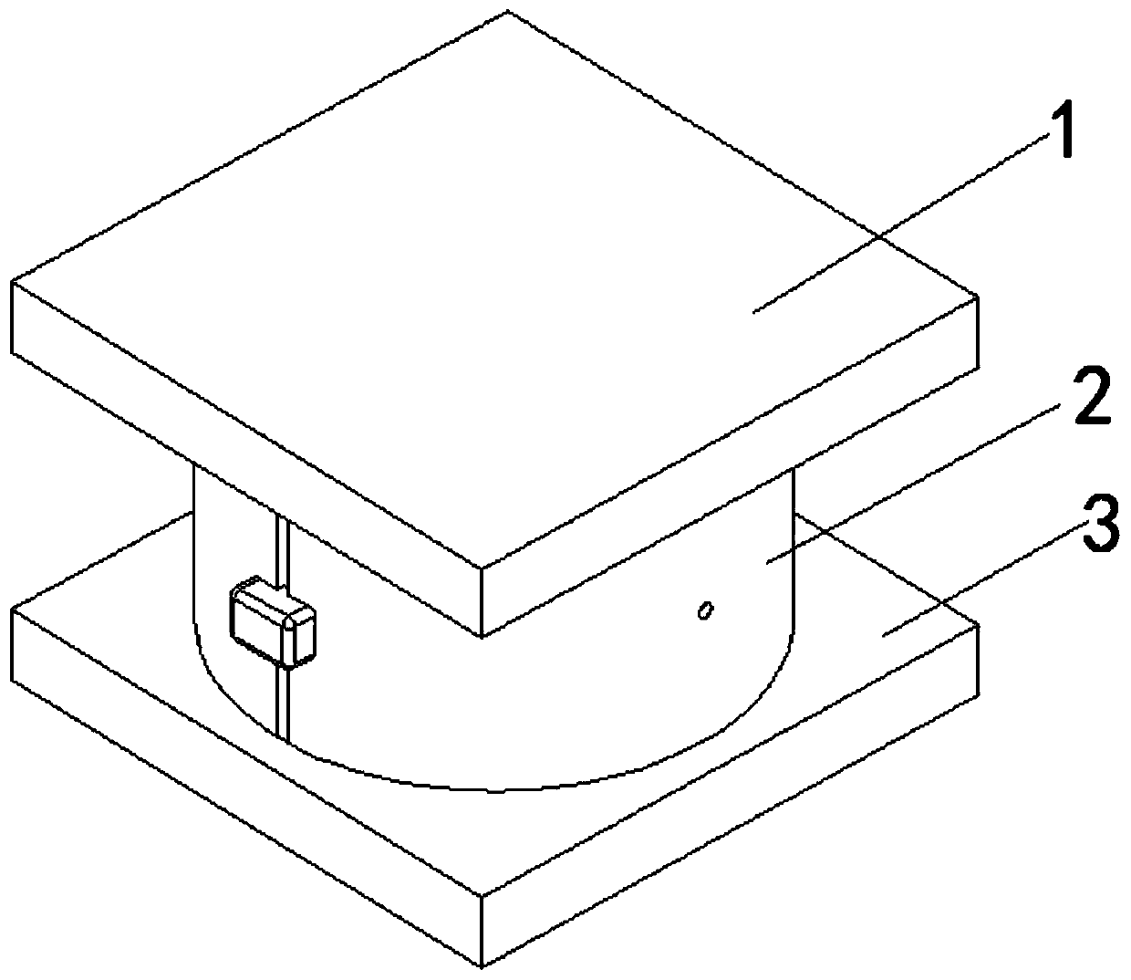
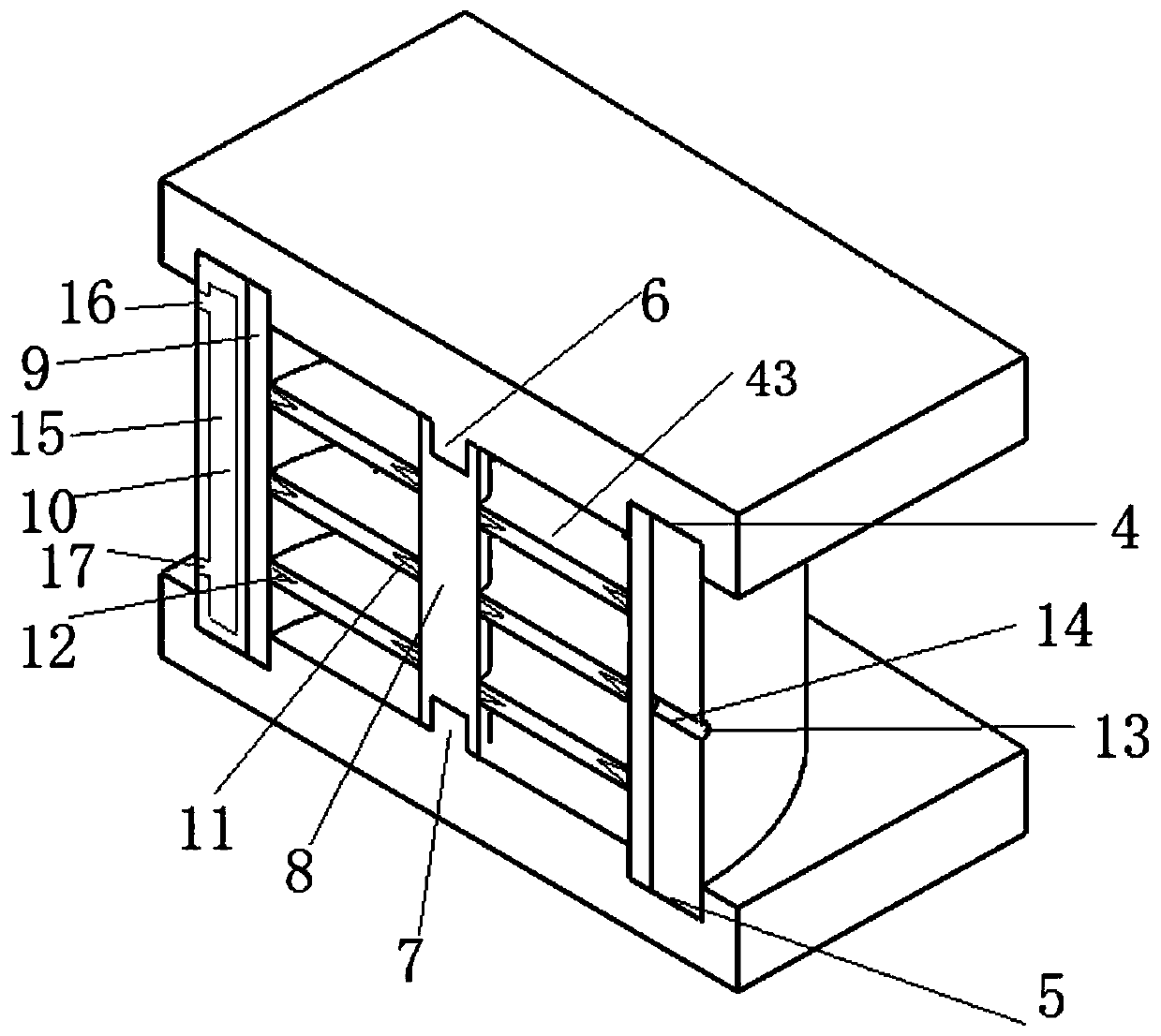
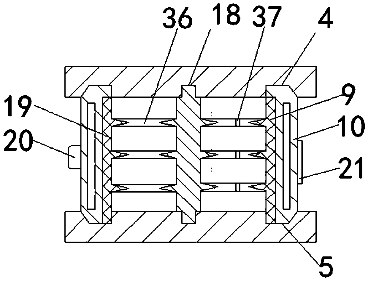
Integrated-type shock insulation supporting seat mould

A seismic isolation bearing and integrated technology, which is applied in the field of integrated seismic isolation bearing molds, can solve problems such as under-vulcanization of the central part of the isolation bearing, increased uniform heating and uniform vulcanization, and affecting the quality of the isolation bearing. , to achieve the effect of shortening the warm-up time, improving product quality, and facilitating installation and disassembly

Active Publication Date: 2019-07-09
广东宇泰制震装备股份有限公司
View PDF5 Cites 1 Cited by
  • Summary
  • Abstract
  • Description
  • Claims
  • Application Information

AI Technical Summary

Problems solved by technology

[0008] Although in order to improve the heating efficiency, the vulcanization temperature can be appropriately increased, but the heat transfer hysteresis of the rubber will still lead to uneven heat transfer, resulting in over-vulcanization in local overheated areas and under-vulcanization in local over-cooled areas, affecting shock isolation Support quality
In particular, due to the increase in the area and number of stacks of large-scale seismic isolation bearings, it is even more difficult to uniformly heat and vulcanize
The central part of the isolation bearing is often under-vulcanized, while the edge part is over-vulcanized, which affects product quality

Method used


Image

  • Integrated-type shock insulation supporting seat mould
  • Integrated-type shock insulation supporting seat mould
  • Integrated-type shock insulation supporting seat mould

Examples


Embodiment Construction

[0055] The technical solutions of the present invention will be clearly and completely described below in conjunction with the accompanying drawings. Apparently, the described embodiments are some of the embodiments of the present invention, but not all of them. Based on the embodiments of the present invention, all other embodiments obtained by persons of ordinary skill in the art without making creative efforts belong to the protection scope of the present invention.

[0056] In the description of the present invention, it should be noted that the terms "center", "upper", "lower", "left", "right", "vertical", "horizontal", "inner", "outer" etc. The indicated orientation or positional relationship is based on the orientation or positional relationship shown in the drawings, and is only for the convenience of describing the present invention and simplifying the description, rather than indicating or implying that the referred device or element must have a specific orientation, ...


PUM


Abstract

The invention belongs to the technical field of shock insulation supporting seat mould, and particularly relates to an integrated-type shock insulation supporting seat mould. The integrated-type shockinsulation supporting seat mould includes an upper mould, a middle mould and a lower mould, wherein the upper mould is placed at the top of the middle mould, the lower mould is placed at the bottom of the middle mould, the middle mould includes a spindle, an inner middle mould and an outer middle mould, the spindle is a cylinder, a first limiting device is movably arranged on the outer cylindrical surface of the spindle, the inner middle mould is an annular column-shaped body, a second limiting device is arranged on the inner cylindrical surface of the inner middle mould, the first limiting device and the second limiting device are used in a matched mode, the outer middle mould is an annular column-shaped body, a pouring opening is formed in the outer cylindrical surface of the outer middle mould, the pouring opening communicates with a pouring channel, the pouring channel penetrates through the inner cylindrical surface of the outer middle mould, a heating oil cavity is formed in theinner part of the outer middle mould, and the outer middle mould arranged on the outer part of the inner middle mould in a sleeving mode. According to the integrated-type shock insulation supportingseat mould, compression of a rubber layer and a steel plate layer and pressing-in of an outer sealing layer and a pencil lead of the rubber layer and the steel plate layer can be manufactured througha set of moulds, all the processes are integrated as a whole, time and labor are saved, cost expenditure of the moulds is reduced, and the application rang is wide.

Description

technical field [0001] The invention belongs to the technical field of shock-isolation support molds, in particular to an integrated shock-isolation support mold. Background technique [0002] The seismic isolation bearing refers to the supporting device set up by the structure to meet the seismic isolation requirements. It is to add a seismic isolation layer between the upper structure and the foundation, install a rubber seismic isolation bearing, and play a soft connection with the ground. Through such a technology , can offset about 80% of the energy of the earthquake. Seismic isolation bearings are important components and basic building materials to achieve foundational isolation, and are widely used in high-intensity earthquake areas and seismic design of important buildings. [0003] The basic structure of the shock-isolation bearing is that according to the design requirements, a layer of rubber sheets and a layer of steel sheets are alternately superimposed togeth...

Claims


Application Information

Patent Timeline
Patent Type & Authority Applications(China)
IPC IPC(8): B29C39/26
CPCB29C39/26
Inventor 郭少得洪嘉维
Owner 广东宇泰制震装备股份有限公司
Why Eureka
Try Eureka