Bottom thread stand structure and sewing machine

A frame structure and bottom thread technology, which is applied in the direction of sewing machine components, sewing machine ring mechanism, sewing equipment, etc., can solve the problems of increasing processing difficulty and processing cost, relatively high precision requirements, and complex overall structure, so as to achieve convenient threading and coordination The effect of low relationship requirements and quick disassembly and assembly

Active Publication Date: 2019-07-09
JACK SEWING MASCH CO LTD
View PDF7 Cites 0 Cited by
  • Summary
  • Abstract
  • Description
  • Claims
  • Application Information

AI Technical Summary

Problems solved by technology

The overall structure is relatively complicated and the cost is high. In order to ensure that the bottom thread frame assembly can be ejected smoothly, it is necessary to ensure the cooperation relationship between the two slide bars 3, the slide bar seat 1 and the bottom thread frame seat 2. Therefore, the precision requirements for the parts are relatively high. High, which increases the processing difficulty and processing cost

Method used


Image

  • Bottom thread stand structure and sewing machine
  • Bottom thread stand structure and sewing machine
  • Bottom thread stand structure and sewing machine

Examples


Embodiment Construction

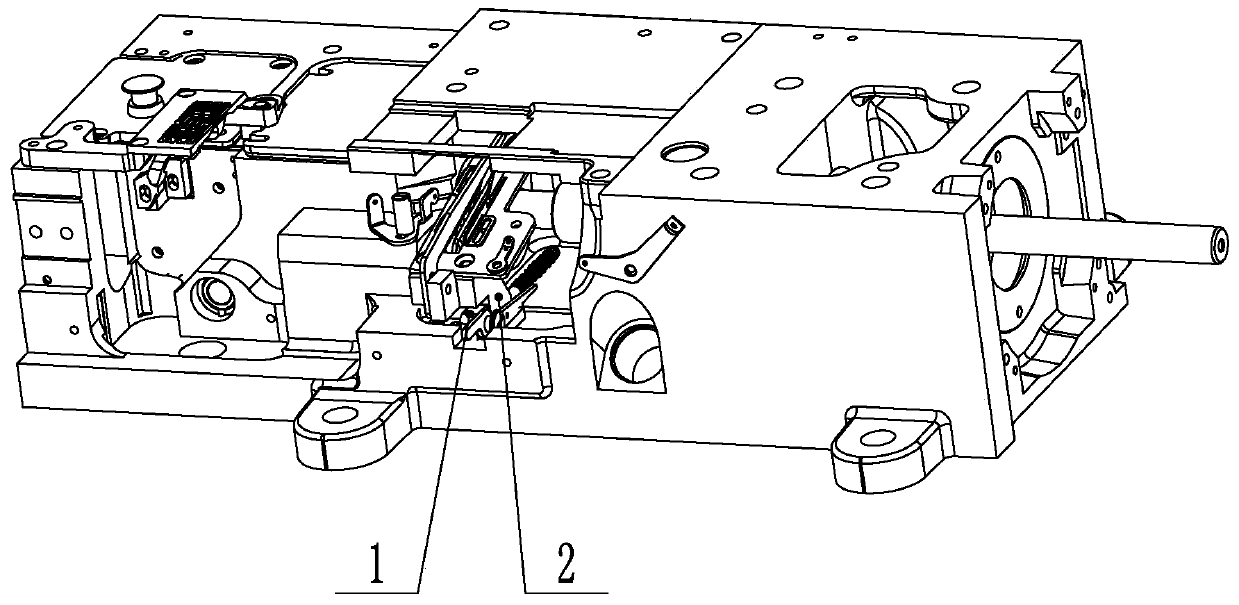
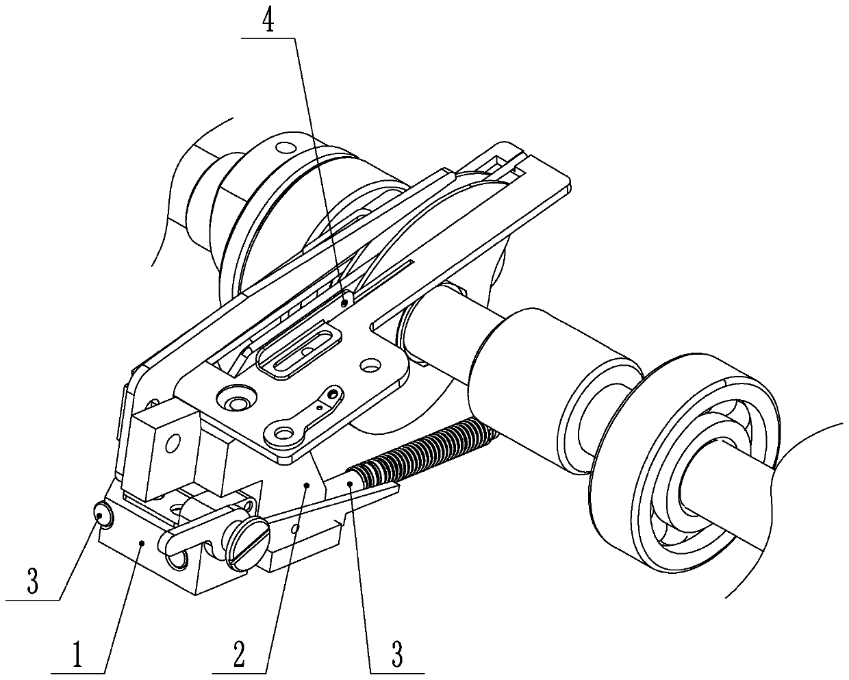
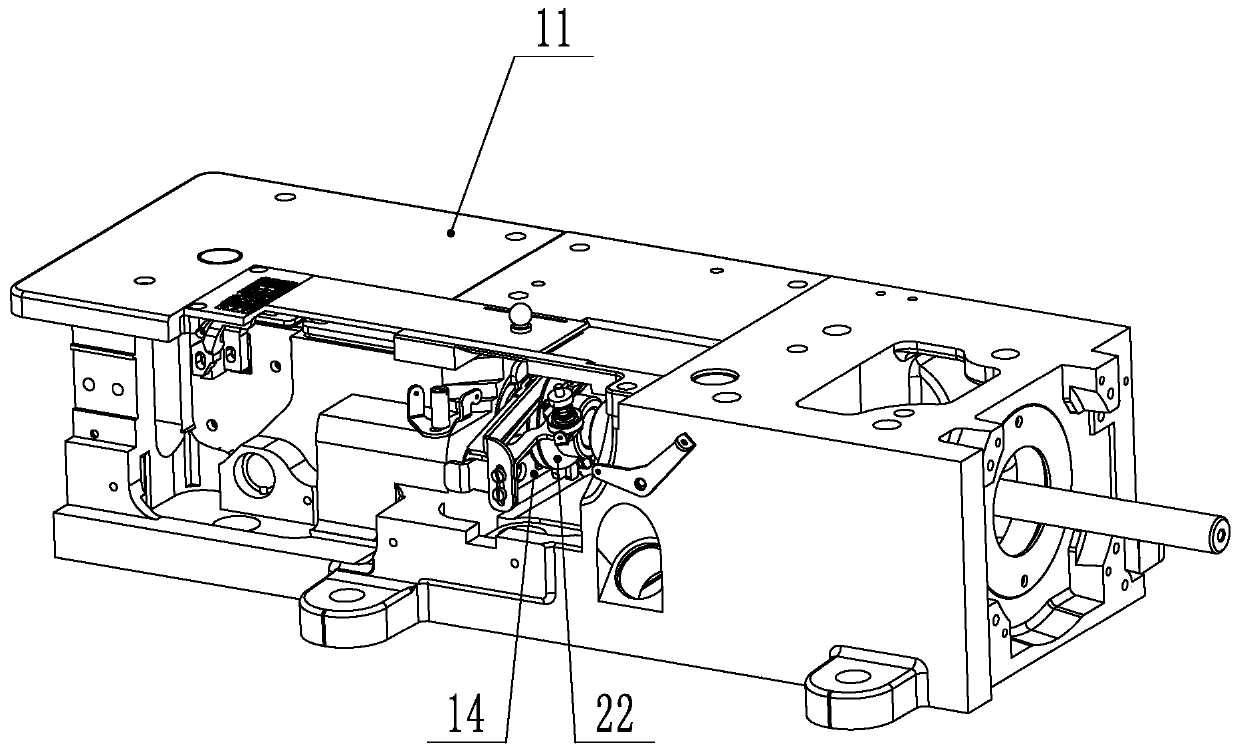
[0037] The present invention will be further described below with specific embodiment, see image 3 -11:

[0038] One of the objects of the present invention is a bobbin frame structure, comprising a bobbin thread frame mounting plate 10, the bobbin thread frame mounting plate 10 includes a horizontal plate and a vertical plate, the horizontal plate is fixed on the casing 11 by screws, and the vertical plate is used for mounting Bottom thread frame assembly 12, backing plate 16 and other parts. Bottom thread frame assembly 12 and driving spring 13 are arranged on the bottom thread frame mounting plate 10, the bottom thread frame assembly 12 and the bottom thread frame mounting plate 10 are slidingly connected, one end of the driving spring 13 is connected on the bottom thread frame mounting plate 10, and the other end Abut against the lower thread frame assembly 12 to generate an outward thrust on the lower thread frame assembly 12, a lower thread frame wrench 14 is arranged ...


PUM


Abstract

The invention belongs to the technical field of sewing equipment and particularly relates to a bottom thread stand structure and a sewing machine. A bottom thread stand component and a driving springare disposed on a bottom thread stand mounting plate; the bottom thread stand component is slidably connected with the bottom thread stand mounting plate; one end of the driving spring is connected tothe bottom thread stand mounting plate, while the other end is abutted to the bottom thread stand component to generate outward push upon the bottom thread stand component; a bottom thread stand lever is arranged below the bottom thread stand component; one end of the bottom thread stand lever is slidably connected with the bottom thread stand mounting plate; a limiter is disposed on the bottom thread stand mounting plate between the bottom thread stand component and the bottom thread stand lever; one end of the limiter is connected with the bottom thread stand lever, while the other end is connected with the bottom thread stand component; one end of the limiter moves with the bottom thread stand lever so as to drive the limiter to rotate, thereby removing the positioning upon the bottomthread stand component; after the limited is returned, the other end of the limiter is connected to the corresponding part of the bottom thread stand component to arrive at positioning. The bottom thread stand structure and the sewing machine have good threading convenience and low production cost.

Description

[0001] Technical field: [0002] The invention belongs to the technical field of sewing equipment, in particular to a bottom thread frame structure and a sewing machine. [0003] Background technique: [0004] The existing lower thread holder assembly is as follows (see figure 1 , 2 ): includes a slide bar seat 1, lower thread holder 2 and two slide bars 3. The bottom thread frame assembly is positioned at the inside during the sewing state, and when threading is required, it needs to be moved to the outside, and the threading hole 4 on the bottom thread frame assembly is moved to the outside to facilitate threading. The overall structure is relatively complicated and the cost is high. In order to ensure that the bottom thread frame assembly can be ejected smoothly, it is necessary to ensure the cooperation relationship between the two slide bars 3, the slide bar seat 1 and the bottom thread frame seat 2. Therefore, the precision requirements for the parts are relatively high...

Claims


Application Information

Patent Timeline
Patent Type & Authority Applications(China)
IPC IPC(8): D05B57/00
CPCD05B57/00
Inventor 田国兵张建波
Owner JACK SEWING MASCH CO LTD
Why Eureka
Try Eureka