Mechanical device damping device of novel improved structure

A technology of mechanical equipment and shock absorption device, applied in the direction of coil spring, non-rotational vibration suppression, etc., can solve the problems of large vibration amplitude of mechanical equipment and poor shock absorption effect of shock absorption equipment, and achieves good shock absorption effect, simple structure, The effect of easy disassembly and installation

Inactive Publication Date: 2019-07-09
天津市旭日昊宇科技发展有限公司
View PDF0 Cites 4 Cited by
  • Summary
  • Abstract
  • Description
  • Claims
  • Application Information

AI Technical Summary

Problems solved by technology

[0002] At present, China's mechanical science and technology are developing rapidly, and mechanical equipment is developing toward large-scale, precision, automation, and complete sets. Vibration will be generated during operation, and the amplitude of the vibration will directly affect the normal operation of the mechanical equipment. This requires certain shock absorption measures for the mechanical equipment to prevent the operation of the mechanical equipment from being affected by the excessive vibration amplitude of the mechanical equipment. However, the existing mechanical equipment either does not have shock absorbing equipment, or the shock absorbing effect of the shock absorbing equipment is very poor. For this reason, we urgently need to propose a new type of mechanical equipment shock absorbing device with improved structure, which is used to solve the problem of excessive vibration amplitude of mechanical equipment. The problem

Method used


Image

  • Mechanical device damping device of novel improved structure
  • Mechanical device damping device of novel improved structure
  • Mechanical device damping device of novel improved structure

Examples


Embodiment Construction

[0014] The following will clearly and completely describe the technical solutions in the embodiments of the present invention with reference to the accompanying drawings in the embodiments of the present invention. Obviously, the described embodiments are only some, not all, embodiments of the present invention.

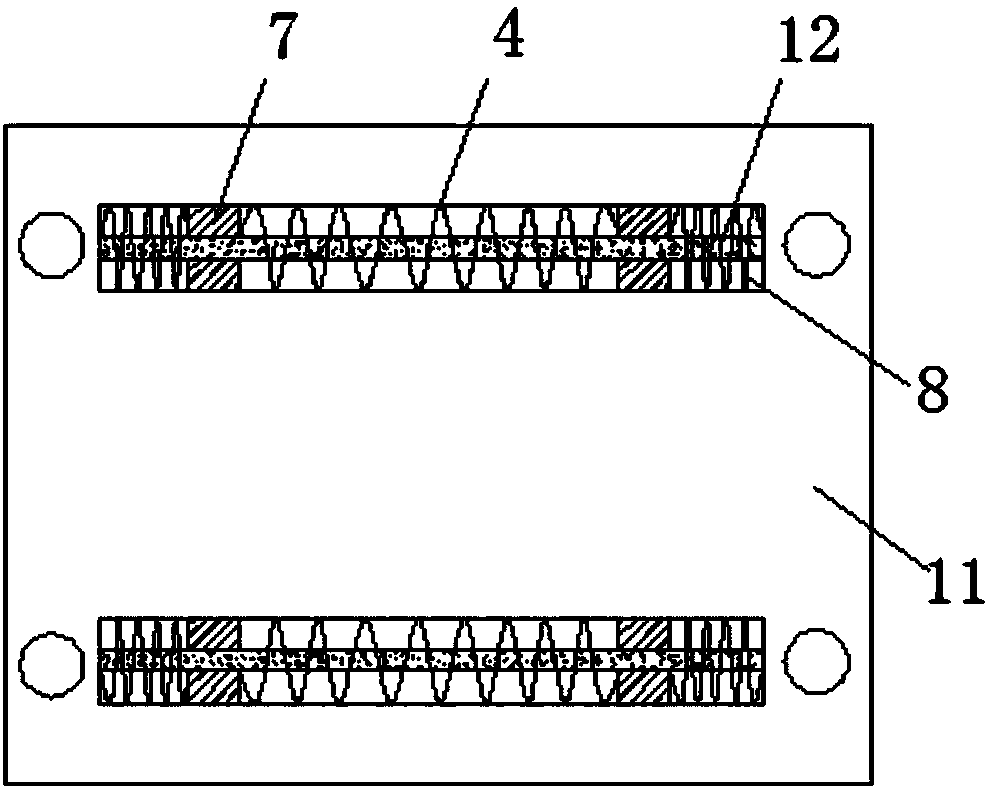
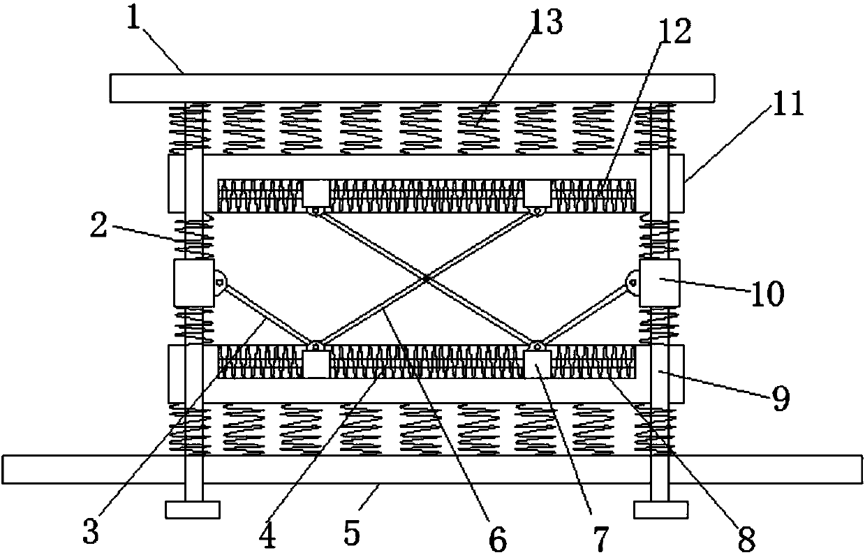
[0015] refer to Figure 1-2 , a new type of mechanical equipment shock absorber with improved structure, including a top plate 1, a mounting plate 11 and a bottom plate 5, the bottom end of the top plate 1 is fixed with four evenly distributed third connecting rods 9, and the bottom ends of the third connecting rods 9 are A bottom plate 5 is slidably connected, and two symmetrical and horizontal mounting plates 11 are arranged between the bottom plate 5 and the top plate 1, and the two mounting plates 11 are slidably connected with four third connecting rods 9, and the two mounting plates 11 are connected to the top plate 1 Evenly and symmetrically distributed fourth...


PUM


Abstract

The invention discloses a mechanical device damping device of a novel improved structure. The damping device comprises a top plate, mounting plates and a bottom plate; four uniformly distributed thirdconnecting rods are fixed to the bottom end of the top plate; the bottom ends of the third connecting rods are connected with the bottom plate in a sliding manner; the two symmetrical horizontal mounting plates are arranged between the bottom plate and the top plate; the two mounting plates are connected with the four third connecting rods in a sliding manner; uniformly symmetrically distributedfourth springs are arranged between the two mounting plates and the top plate and between the two mounting plates and the bottom plate; symmetrical rectangular sliding grooves are formed in each mounting plate; horizontal fourth connecting rods are arranged in each rectangular sliding groove; the two ends of the fourth connecting rods are fixed on the inner walls of the rectangular sliding grooves; two symmetrically distributed first sliding blocks are arranged in each rectangular sliding groove; the first sliding blocks are connected onto the fourth connecting rods in a sliding manner; and asecond spring is connected between the two first sliding blocks. The damping device is good in damping effect, simple in structure, easy to mount and dismount, low in cost, and high in applicability.

Description

technical field [0001] The invention relates to the technical field of shock absorbing devices, in particular to a novel and improved structure shock absorbing device for mechanical equipment. Background technique [0002] At present, China's mechanical science and technology are developing rapidly, and mechanical equipment is developing toward large-scale, precision, automation, and complete sets. Vibration will be generated during operation, and the amplitude of the vibration will directly affect the normal operation of the mechanical equipment. This requires certain shock absorption measures for the mechanical equipment to prevent the operation of the mechanical equipment from being affected by the excessive vibration amplitude of the mechanical equipment. However, the existing mechanical equipment either does not have shock absorbing equipment, or the shock absorbing effect of the shock absorbing equipment is very poor. Therefore, we urgently need to propose a new type o...

Claims


Application Information

Patent Timeline
Patent Type & Authority Applications(China)
IPC IPC(8): F16F15/04F16F15/02
CPCF16F15/02F16F15/04F16F2238/026
Inventor 刘凯
Owner 天津市旭日昊宇科技发展有限公司
Why Eureka
Try Eureka