
Upper air admission combustor

A technology for burners and air intake ends, applied in the direction of burners, gas fuel burners, combustion methods, etc., can solve problems such as nozzle clogging, and achieve the effect of ensuring normal operation and not being easily heated

Pending Publication Date: 2019-07-09
NINGBO FOTILE KITCHEN WARE CO LTD
View PDF4 Cites 0 Cited by
  • Summary
  • Abstract
  • Description
  • Claims
  • Application Information

AI Technical Summary

Problems solved by technology

[0006] In addition, because the upward air intake burner ejector tube, nozzle, burner fire cover, etc. are located above the panel, so many parts are piled up on the panel, which also brings a lot of trouble to the panel cleaning. There is a problem of nozzle clogging; therefore, it is necessary to design an upward air intake burner, which is easy to clean on the basis of compact structure and improved ejection ability, and can effectively prevent the problems of fire cover clogging and nozzle clogging

Method used


Image

  • Upper air admission combustor
  • Upper air admission combustor
  • Upper air admission combustor

Examples


Embodiment Construction

[0031] The present invention will be further described in detail below in conjunction with the accompanying drawings and embodiments.

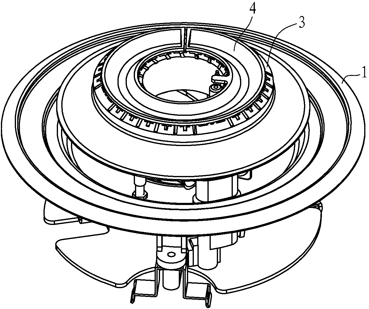
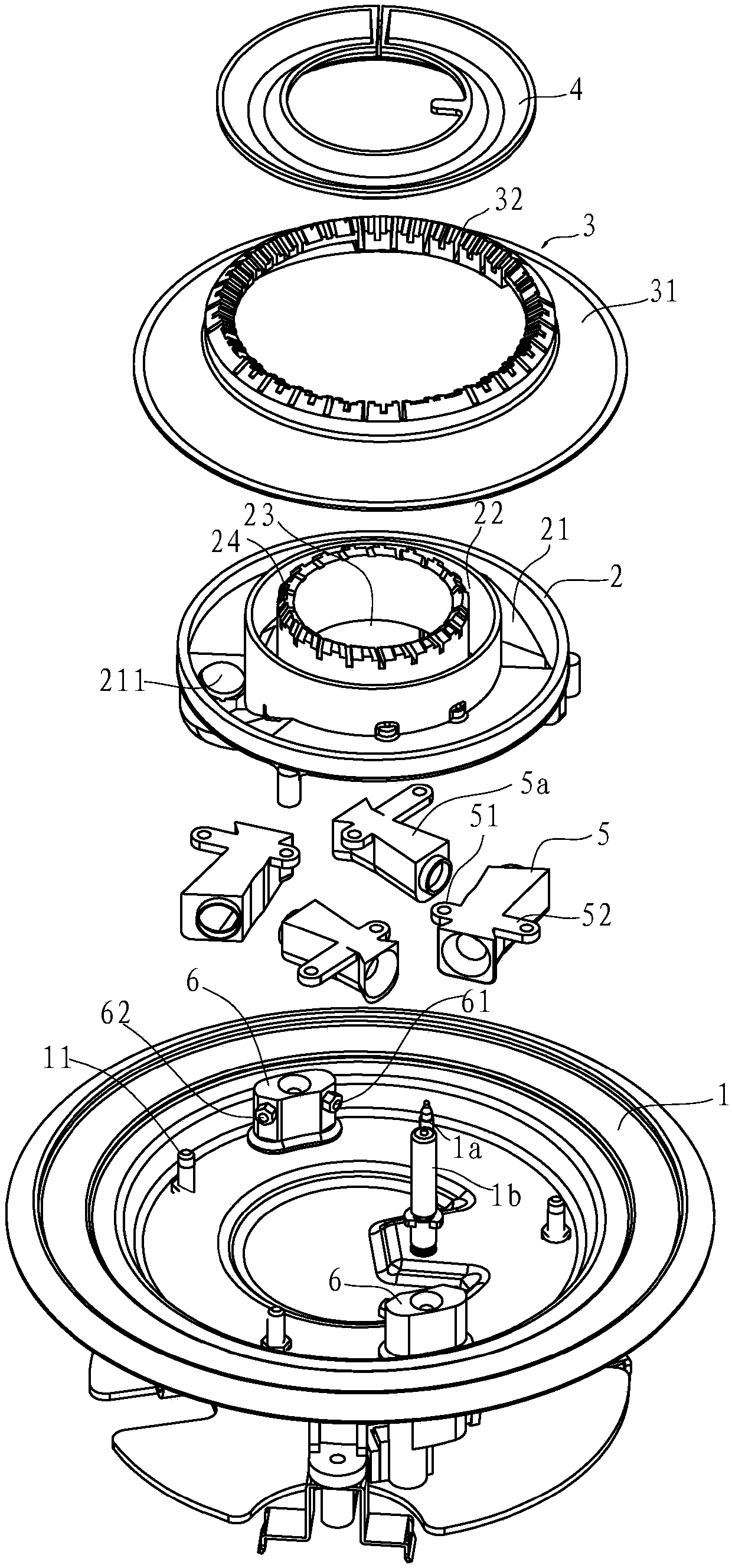
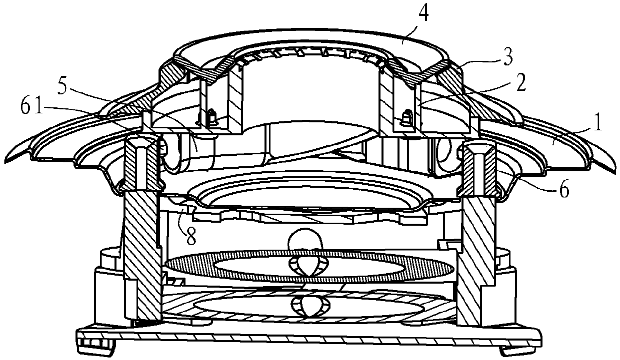
[0032] Such as figure 1 and figure 2 As shown, the upper air intake burner in this embodiment includes a liquid pan 1, an air mixing seat 2, a heat sink 8 and a fire cover. The liquid pan 1 is provided with two separately arranged nozzle seats 6, and each nozzle seat 6 There is a first nozzle 61 and a second nozzle 62 on it; a thermocouple 1a and an ignition needle 1b are arranged on the liquid pan 1 .

[0033] The air mixing seat 2 is arranged on the upper end surface of the liquid holding tray 1, and the upper end surface of the air mixing seat 2 has an annular inner air mixing groove 22 and an outer air mixing groove 21 positioned outside the inner air mixing groove 22, and the inner air mixing groove 22 has at least Two inner air inlets 221 are opened, and two outer air inlets 211 are opened on the outer air mixing tank 21. The lower en...


PUM


Abstract

The invention discloses an upper air admission combustor. The combustor comprises a liquid containing disc (1), a gas mixing base (2) and a fire cap arranged on the gas mixing base (2). Spray nozzle holders (6) are arranged on the liquid containing disc (1). The spray nozzle holders (6) are provided with spray nozzles correspondingly. The gas mixing base (2) is arranged on the upper end surface ofthe liquid containing disc (1) and provided with ejection pipes. The air inlet ends of the ejection pipes correspond to the spray nozzles. The fire cap is arranged on the gas mixing base (2). The upper air admission combustor is characterized in that the combustor further comprises a heat dissipating piece (8) arranged on the lower end surface of the liquid containing disc (1); and the heat dissipating piece can rapidly take heat on the upper end surface of the liquid containing disc away from a position under the liquid containing disc through air motion, accordingly, it is guaranteed that the spray nozzle holders are not prone to being heated, and normal operation of the spray nozzles is guaranteed.

Description

technical field [0001] The invention relates to a cooker burner, which belongs to the technical field of gas burning equipment. Background technique [0002] Existing cooker burners can be divided into upper air intake burners and lower air intake burners according to the injection method of primary air. The air intake burner has high primary air injection efficiency and sufficient premixing, but it is easy to turn off the flame when the cabinet door is opened and closed, and if the cabinet does not open the air inlet, there will be a hidden danger of insufficient primary air. [0003] The primary air required by the upward-inlet burner enters the injection tube from the top of the cooking surface. The limitation of the primary air induction structure of this type of burner requires its overall structure to be compact, and the structure of the injection tube and the mixing chamber is simplified. The primary air, The premixing is still not very sufficient, resulting in weak ...

Claims


Application Information

Patent Timeline
IPC IPC(8): F24C3/08F24C15/14F23D14/04F23D14/58F23D14/64
CPCF24C3/085F24C15/14F23D14/04F23D14/58F23D14/64
Inventor 郑军妹王帅东邵海忠吴丽波
Owner NINGBO FOTILE KITCHEN WARE CO LTD
Learn More