Operating elements for electrically controlled machines

A technology of operating components and electric control, applied in the direction of control mechanisms, control components, electrical components, etc., can solve problems such as expensive, difficult to achieve coupling, and easy to fail in coupling

Active Publication Date: 2022-05-27
KEBA AG
View PDF6 Cites 0 Cited by
  • Summary
  • Abstract
  • Description
  • Claims
  • Application Information

AI Technical Summary

Problems solved by technology

[0003] The operating unit known from AT512521 B1 has the disadvantage that the operating element, which executes commands by pressing, pulling, pivoting, etc., must have a corresponding mechanical coupling to the switch
Such coupling is prone to failure and expensive
Moreover, such a coupling is difficult to implement, for example, in Ex areas

Method used


Image

  • Operating elements for electrically controlled machines
  • Operating elements for electrically controlled machines
  • Operating elements for electrically controlled machines

Examples


Embodiment Construction

[0047] First of all, it should be pointed out that in the different described embodiments, the same components are provided with the same reference numerals or the same component names, wherein the disclosure contained in the entire specification can be transferred to those with the same reference numerals. Symbols or on the same part with the same component name. The position descriptions selected in the description, such as upper, lower, lateral, etc., also refer to the directly described and illustrated figures and these position descriptions are transferred meaningfully to the new position when the position is changed.

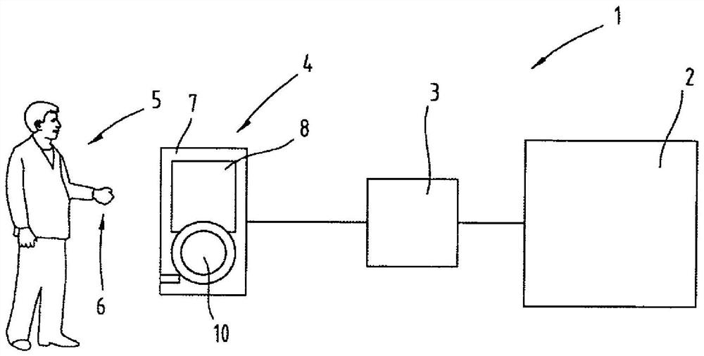
[0048] figure 1 A schematic diagram of a production plant 1 is shown with an electrically controlled machine 2 , a control device 3 for the machine 2 and operating elements 4 for inputting control commands into the control device 3 by a machine operator 5 . In particular, provision is made for the machine operator 5 to actuate the operating element 4 with...


PUM

PropertyMeasurementUnit
diameteraaaaaaaaaa

Abstract

The invention relates to an operating element (4) for an electrically controlled machine (2), said operating element having an operating element body (7) and a control device (3) for inputting commands to said machine (2) ) in the rotary wheel (10), wherein the rotary wheel (10) is rotatably arranged on the operating element body (7) around the rotation axis (12) and is surrounded by a peripheral surface (11), the peripheral The surface has a predetermined local mean diameter (13) in a direction perpendicular to the axis of rotation (12), on which peripheral surface (11) the rotating wheel (10) is grasped and Rotation, wherein the peripheral surface (11) of the rotary wheel (10) has at least two manipulation sections (14, 15), the manipulation sections have different surface structures (17), the manipulation sections ( At least one of the actuation sections (14, 15) is assigned a sensor region (18, 19) of a sensor element (21, 22), and at least one of the actuation sections (14, 15) is assigned Different machine functions for inputting at least one command into the control device (3) are provided, and the at least two manipulation sections (14, 15) are arranged on the circumference of the rotary wheel (10) ( 11) is arranged such that the actuation section can be detected by the machine operator (5) with the hand (6) and / or his fingers.

Description

technical field [0001] The invention relates to an operating element for inputting commands into a control device of an electrically controlled machine. Background technique [0002] An operating unit for an injection molding machine is known from AT512521B1. The actuating unit has an actuating element for triggering at least one movement of the drive unit of the injection molding machine, wherein the actuating element is movable from a starting position into a triggering region that triggers the movement of the drive unit. The trigger area has many intermediate positions between the initial position and the maximum position. The speed of the triggered movement of the drive unit depends on the distance between the selected intermediate position of the operating element and the initial position. The movement of a plurality of drive units can be triggered by the operating element, wherein the drive unit actuated by the operating element is replaced by pressing, pulling, pivo...

Claims


Application Information

Patent Timeline
Patent Type & Authority Patents(China)
IPC IPC(8): G06F3/0362
CPCB29C45/17B29C45/76G05B19/042G05B19/427G06F3/00G06F3/03G06F3/0362G06F3/04847B25J13/02G05G1/08G05G1/10G05G9/047H01H3/08H01H13/10H01H13/14
Inventor H·菲舍尔B·哈克尔W·马尔
Owner KEBA AG
Why Eureka
Try Eureka