
Eureka
For R&D, Eureka makes reading and utilizing patents & technical documents easy.
Eureka AIR
Designed for self-driven R&D workflows. Generate viable solutions, solve complex R&D challenges, empower your innovation with AI.

Eureka Materials
Designed for material experts only. Revolutionize your material R&D, from search, analyze, to developing new materials.

TechResearch
Generate reliable direction feasibility study reports for your R&D in just a few steps.

TechSeek
Discover and master advanced knowledge NOW. Basics, ideas, possibilities, all at once.

TechMind
As an expert in R&D Theories, TechMind can generates customized viable solutions instantly.

TechRisk
Analyze your overall solution with one click, know your potential R&D risks in advance.

TechMonitor
Get weekly tech updates, stay abreast of the latest tech innovations and key insights.
Bifurcated silicone airway stent
A silicone and bifurcated technology, applied in the field of medical devices, can solve problems such as difficulty in adjusting the angle of the stent, damage to the inner wall of the human body cavity, etc., and achieve the effects of easy adjustment, reduced tension, and reduced damage
- Summary
- Abstract
- Description
- Claims
- Application Information
AI Technical Summary
Problems solved by technology
Method used
Image

Examples
Embodiment 1
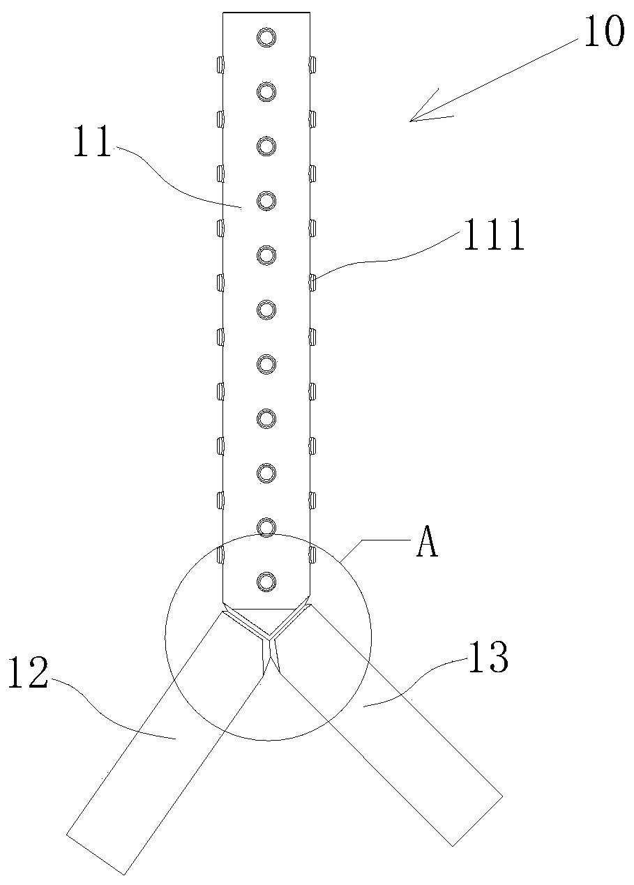
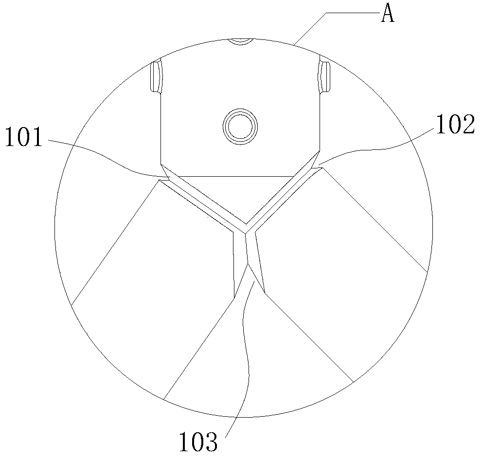
[0022] refer to Figure 1 to Figure 5 , a bifurcated silicone stent 10, comprising a stent main body 11, a first branch 12 and a second branch 13 connected through the stent main body 11, the stent main body 11, the first branch 12 and the second branch 13 form a Y-shaped structure; the The tube wall thickness of the bracket main body 11, the first branch 12 and the second branch 13 is 1.3 millimeters; 11 and the second branch 13 connection, the first branch 12 and the second branch 13 connection extending the first slot 101, the second slot 102 and the third slot 103, between the edges of the first slot 101 The distance L1 between them is 1.5 millimeters, the minimum distance between its inner wall and the inner wall of the bifurcated silicone stent 10 is 0.4 meters, and the minimum distance L2 between the connection between the main body 11 of the stent and the inner wall of the first branch 12 is 0.5 millimeters; The distance between the two edges of the second slot 102 is...
Embodiment 2
[0035] refer to Figure 6 , a bifurcated silicone stent 20, comprising a stent main body 21 and a first branch 22 connected through the side wall of the stent main body 21, the tube wall thickness of the stent main body 21 and the first branch 22 is 1.0 mm, bifurcation The outer wall of the type silicone bracket 20 is provided with a first slot 201 extending along the junction of the bracket main body 21 and the first branch 22, the distance between the two sides of the first slot 201 is 0.5 mm, and the inner wall is in line with the bifurcated type. The minimum distance between the inner walls of the silicone stent 20 is 0.1 mm, and the minimum distance between the connection between the stent main body 21 and the inner wall of the first branch 22 is 0.2 mm.
[0036] The bifurcated silicone stent 20 provided in this embodiment is suitable for treating lesions in branch blood vessels of the human body.
[0037] It should be noted that the bifurcated silicone stent provided by...
PUM
 Abstract
Description
Claims
Application Information
 - R&D Engineer
- R&D Manager
- IP Professional
- Industry Leading Data Capabilities
- Powerful AI technology
- Patent DNA Extraction
Browse by: Latest US Patents, China's latest patents, Technical Efficacy Thesaurus, Application Domain, Technology Topic, Popular Technical Reports.
© 2024 PatSnap. All rights reserved.Legal|Privacy policy|Modern Slavery Act Transparency Statement|Sitemap|About US| Contact US: help@patsnap.com