
Portable photovoltaic cleaning robot

A cleaning robot, portable technology, applied in the field of machinery, can solve the problems of automatic string crossing, large deformation of components, cracks in the glass panel of photovoltaic modules, etc.

Active Publication Date: 2019-07-12
深圳市晟鑫能源科技有限公司
View PDF7 Cites 6 Cited by
  • Summary
  • Abstract
  • Description
  • Claims
  • Application Information

AI Technical Summary

Problems solved by technology

[0002] The traditional way of cleaning solar photovoltaic modules is to clean them one by one with a water gun or a brush. The method of manual wiping can indeed effectively solve the problem of cleaning the mirror surface, but this cleaning method is labor-intensive and costly, and it is very inconvenient to clean. , can not be cleaned frequently, management is difficult, different operators have different strengths, and different pressures on the components, which will cause excessive deformation of the components and cause cracks in the glass panels of photovoltaic modules. Another disadvantage is that manual dry cleaning of components is not effective. Good, often due to too much dust on the mop, some traces are left on the surface of the component, causing a large area of ​​shadows
Existing portable photovoltaic module cleaning equipment can be controlled by remote control, which solves the defects of manual cleaning, but it can only clean a single string, and people need to follow the machine, and cannot automatically cross strings. It requires manpower to carry the equipment, which is time-consuming It is laborious, and the current portable photovoltaic module cleaning equipment on the market uses a single brush roller for cleaning, resulting in insufficient cleanliness of a single cleaning and low comprehensive cleaning efficiency

Method used


Image

  • Portable photovoltaic cleaning robot
  • Portable photovoltaic cleaning robot
  • Portable photovoltaic cleaning robot

Examples


Embodiment Construction

[0040] The specific embodiments of the present invention will be further described below in conjunction with the accompanying drawings.

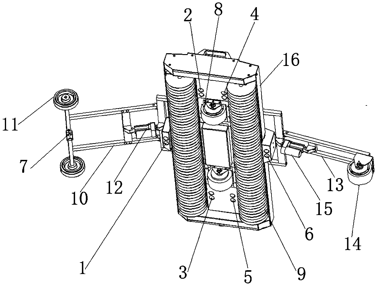
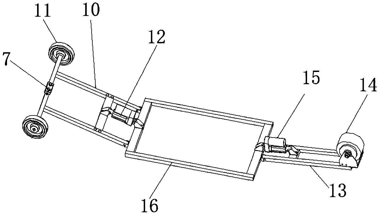
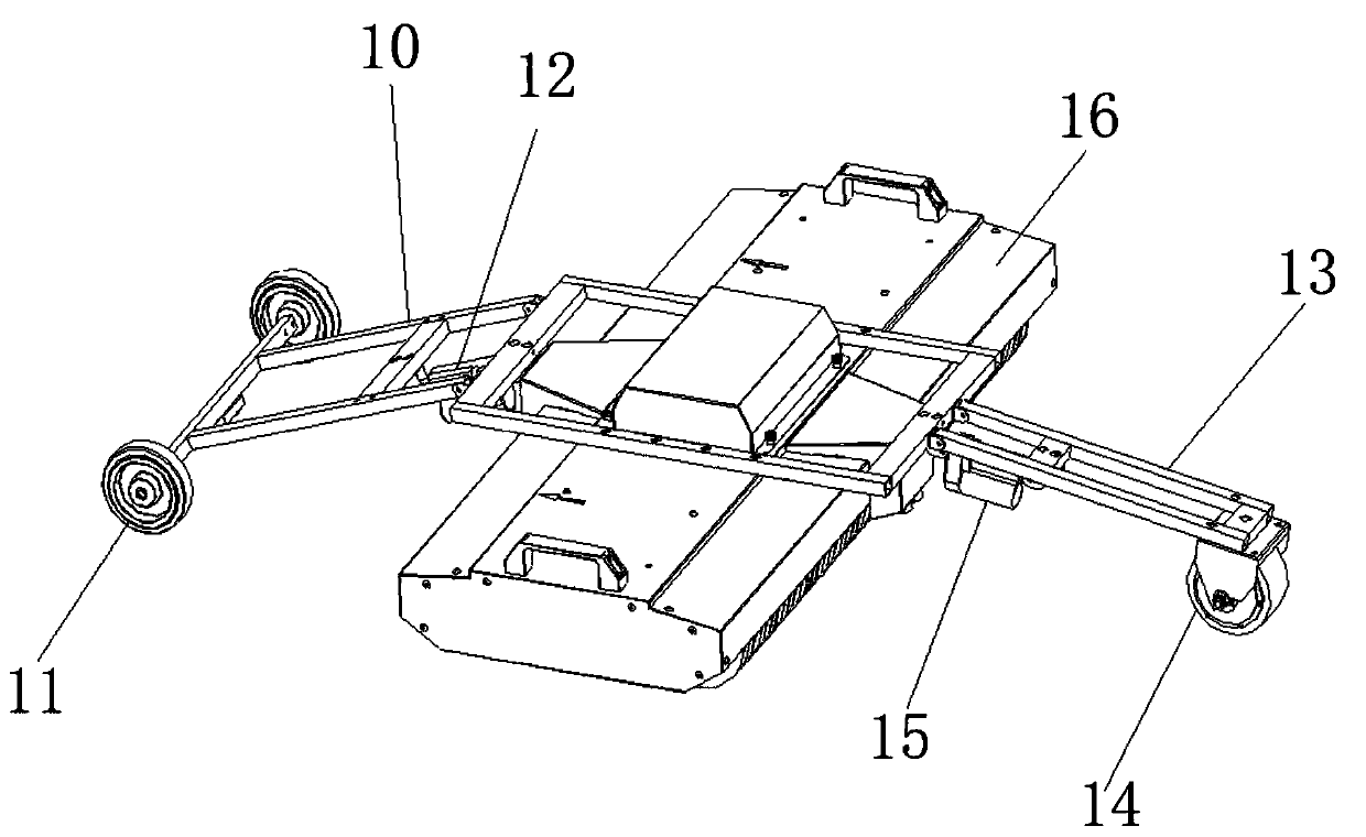
[0041] Such as Figure 1~4 As shown, a portable photovoltaic cleaning robot includes a cleaning robot, and the cleaning robot includes a robot frame 16. Two brush rollers 9 arranged side by side are arranged on the bottom of the robot frame, and two brush rollers are arranged between the two brush rollers. A first hub motor 8; a front auxiliary arm 10 is installed on the front of the robot frame, and a first telescopic device 12 for adjusting the rotation angle of the front auxiliary arm is installed on the front auxiliary arm, and an idler is installed on both sides of the front auxiliary arm. Wheel 11; a rear auxiliary arm 13 is installed on the rear portion of the robot frame, and a second telescopic device 15 for adjusting the angle of rotation of the rear auxiliary arm is installed on the rear auxiliary arm, and a second wheel hub motor...


PUM


Abstract

The invention relates to the field of machinery, in particular to a photovoltaic cleaning robot. The portable photovoltaic cleaning robot comprises a cleaning robot. The cleaning robot comprises a robot frame. Two brush rollers which are arranged in parallel are installed on the lower portion of the robot frame. By means of the design, the portable photovoltaic cleaning robot is provided, cleaningof operation and maintenance equipment of a photovoltaic power station becomes lightweight, the portable photovoltaic cleaning robot is mainly applied to the flat type roof photovoltaic power station, the power station does not need to be improved, and the total cost of installation and cleaning of the operation and maintenance equipment of the photovoltaic power station is reduced. The machine runs on photovoltaic assemblies, the automatic falling-prevention function is fulfilled, and the safe cleaning work of the robot is guaranteed. The intensity of pressure applied to the assemblies is low, no damage is caused, the purpose of automatically crossing a maintenance channel between each photovoltaic assembly array and the adjacent photovoltaic assembly array can be achieved, and manual carrying is not required.

Description

technical field [0001] The invention relates to the mechanical field, in particular, to a photovoltaic cleaning robot. Background technique [0002] The traditional way of cleaning solar photovoltaic modules is to clean them one by one with a water gun or a brush. The method of manual wiping can indeed effectively solve the problem of cleaning the mirror surface, but this cleaning method is labor-intensive and costly, and it is very inconvenient to clean. , can not be cleaned frequently, management is difficult, different operators have different strengths, and different pressures on the components, which will cause excessive deformation of the components and cause cracks in the glass panels of photovoltaic modules. Another disadvantage is that manual dry cleaning of components is not effective. Good, often because the mop is stained with too much dust, leaving some traces on the surface of the component, resulting in a large area of ​​shadows. Existing portable photovoltai...

Claims


Application Information

Patent Timeline
IPC IPC(8): B08B1/04H02S40/10
CPCH02S40/10B08B1/32Y02E10/50Y02B10/10
Inventor 高新强莫灵勇张宁郭林茂
Owner 深圳市晟鑫能源科技有限公司
Learn More