Rotary robot welding fixture and working method thereof

A robotic welding and rotary technology, applied in welding equipment, auxiliary welding equipment, welding/cutting auxiliary equipment, etc., can solve the problems of low utilization of space, time-consuming and laborious, low degree of automation, etc., and achieve accurate welding position. , the use of time-saving and labor-saving, high degree of automation effect

Active Publication Date: 2019-07-12
昆山高科创志机器人自动化有限公司
View PDF5 Cites 8 Cited by
  • Summary
  • Abstract
  • Description
  • Claims
  • Application Information

AI Technical Summary

Problems solved by technology

[0005] The purpose of the present invention is to solve the problem that the existing robot welding jig is time-consuming and labor-intensive in use, the degree of automation of the work is low, and the existing robot welding jig has a low capacity for clamping and fixing the robot parts when in use, and the utilization of space The efficiency is low, and the clamping and fixi

Method used


Image

  • Rotary robot welding fixture and working method thereof
  • Rotary robot welding fixture and working method thereof
  • Rotary robot welding fixture and working method thereof

Examples


Example Embodiment

[0046] The technical solutions of the present invention will be clearly and completely described below in conjunction with embodiments. Obviously, the described embodiments are only a part of the embodiments of the present invention, rather than all the embodiments. Based on the embodiments of the present invention, all other embodiments obtained by those of ordinary skill in the art without creative work shall fall within the protection scope of the present invention.
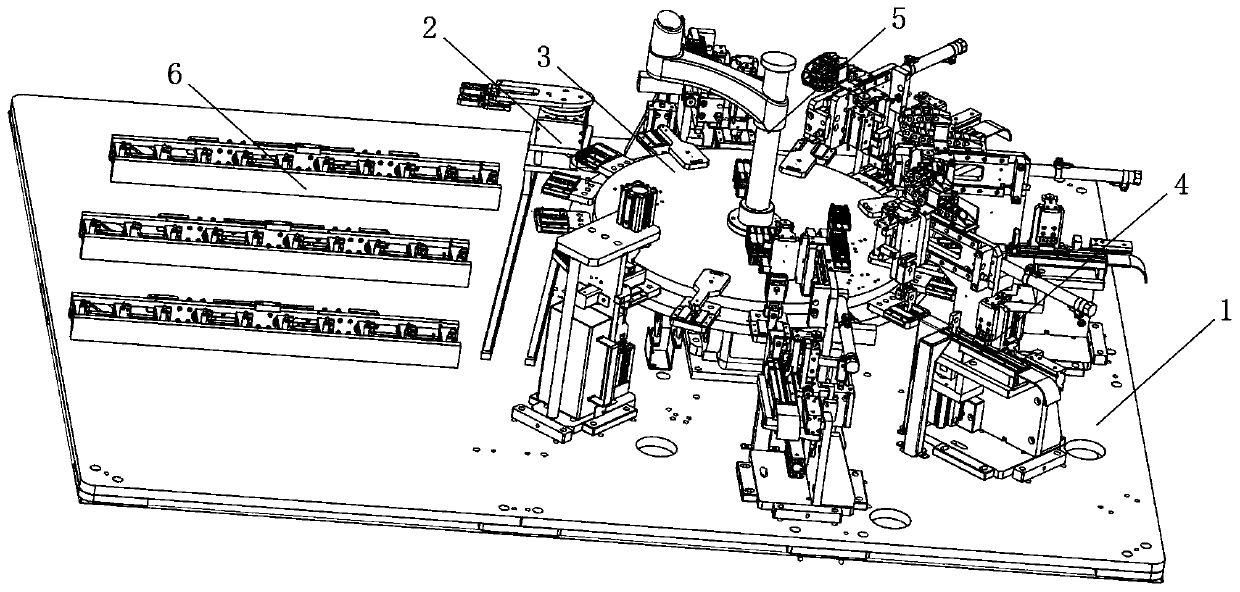
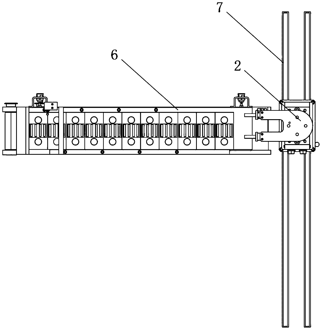
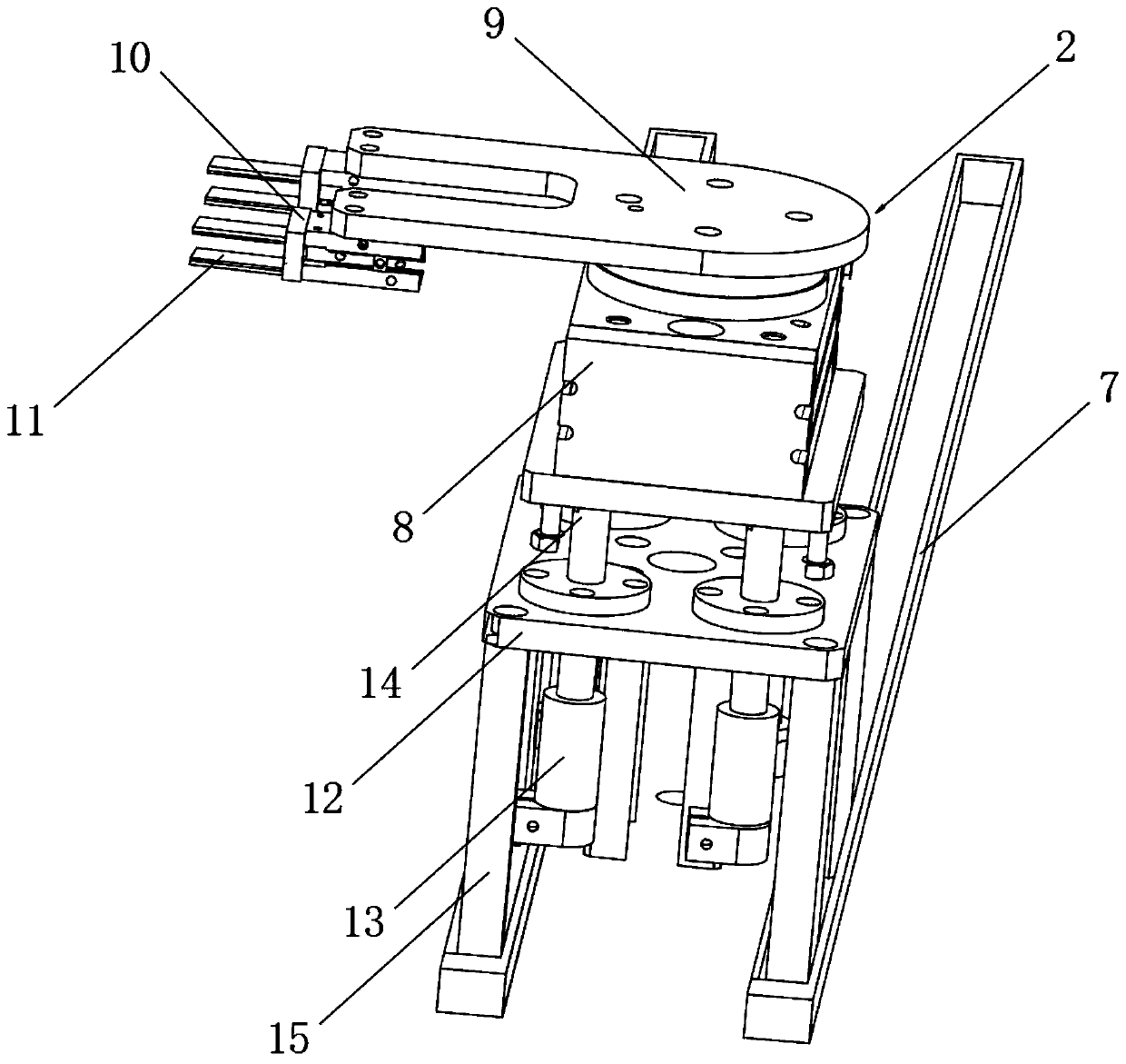
[0047] See Figure 1-14 As shown, a rotary robot welding fixture includes a swinging table 1, a front clamping seat 2, a rear chuck 3, and a side pressing seat 4. The front clamping seat 2 is arranged above the swinging table 1, and the front clamping seat 2 is one A circular rear chuck 3 is arranged on the side, and several side pressing seats 3 are arranged on the edge of the rear chuck 3 in an equal arc;

[0048] A first motor 8 is arranged above the front clamp base 2, and a rotating plate 9 is rotatably conne...


PUM


Abstract

The invention discloses a rotary robot welding fixture comprising an arranging and installing table, a front clamping seat, a rear chuck and side pressure seats. The front clamping seat is arranged above the arranging and installing table, one side of the front clamping seat is provided with the circular rear chuck, and the multiple side pressure seats are arranged at the edge of the rear chuck inan equal-radian manner. A first motor is arranged above the front clamping seat. The rotary robot welding fixture has the beneficial effects that when a welding mechanism performs welding work, a fourth motor drives robot components on a clamping and connecting seat to rotate to achieve fine adjustment of the positions, and it is ensured that the welding work of the welding structure on the robotcomponents is more precise in position and higher in efficiency; and the automatic degree of rotary clamping fixing work by the welding fixture on the robot components is higher, and much time and labor are saved in the using process. Four second motors drive the front clamping seat to move in two mounting frames, a plurality of first hob gears cooperate with a gear to rotate to ensure that the front clamping seat and the robot components are adjusted and moved more smoothly and securely, and collision and abrasion between all parts of the front clamping seat are reduced.

Description

technical field [0001] The invention relates to a welding jig, in particular to a rotary robot welding jig and a working method thereof, belonging to the technical field of protection device applications. Background technique [0002] With the rapid development of people's living standards, robots are used more and more widely in daily life, such as sweeping robots used in households, intelligent processing robots used in factories, etc. There are many kinds of robots and different types. [0003] When the robot is being processed, it is necessary to separate the various parts of the robot for welding processing. When welding the robot parts, the welding fixture is indispensable. Its main function is to clamp and fix the robot parts, so that the welding equipment can be used for robot parts. Welding process. [0004] There are still many deficiencies in the existing robot welding fixtures when they are in use. The existing robot welding fixtures are time-consuming and labor...

Claims


Application Information

Patent Timeline
IPC IPC(8): B23K37/04B23K37/047B23K37/00
CPCB23K37/00B23K37/0443B23K37/047
Inventor 刘萍张书玮
Owner 昆山高科创志机器人自动化有限公司
Why Eureka
Try Eureka