Historical map utilization method based on visual robot

A robot and map technology, applied in applications, instruments, manipulators, etc., can solve problems such as operation failure

Active Publication Date: 2019-07-12
AMICRO SEMICON CORP
View PDF2 Cites 10 Cited by
  • Summary
  • Abstract
  • Description
  • Claims
  • Application Information

AI Technical Summary

Problems solved by technology

[0002] Every time a traversal is completed in the same working area, the robot often re-builds the map or updates it incrementally. Change and fail

Method used


Image

  • Historical map utilization method based on visual robot
  • Historical map utilization method based on visual robot
  • Historical map utilization method based on visual robot

Examples


Embodiment Construction

[0015] The technical solutions in the embodiments of the present invention will be described in detail below with reference to the drawings in the embodiments of the present invention.

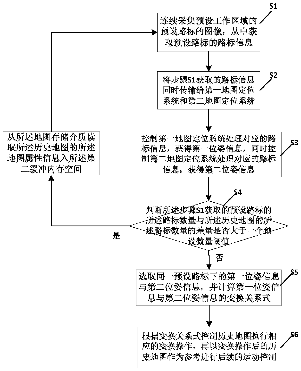
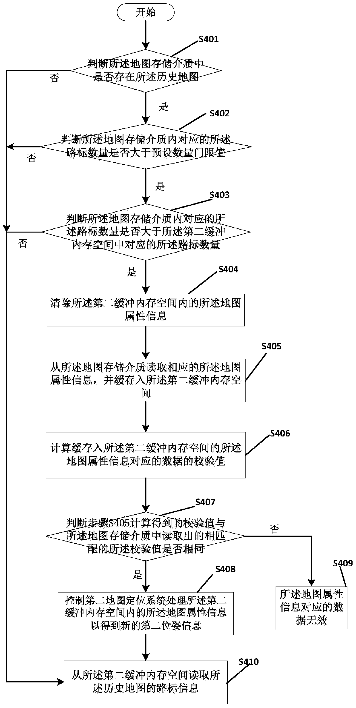
[0016] An embodiment of the present invention provides a historical map utilization method based on a visual robot. The historical map utilization method is used to control the first map positioning system based on the current map and the second map positioning system based on the historical map to work independently of each other. When the map positioning system After the front end of the system generates landmark information, it is sent to the positioning system of the historical map and the positioning system of the current map for conversion processing. The positioning information of the visual robot is generated by the aforementioned map positioning system. Specifically: according to the landmark information of the historical map, locate the current coordinates and current direction of the...


PUM


Abstract

The invention discloses a historical map utilization method based on a visual robot. The historical map utilization method comprises the following steps of 1, controlling the visual robot to continuously acquire images of preset road signs in a preset working area and acquire road sign information of the preset road signs; 2, transmitting the acquired road sign information to a first map positioning system and a second map positioning system simultaneously; 3, controlling the first map positioning system and the second map positioning system to process corresponding road sign information so asto obtain first pose information and second pose information; 4, selecting the first pose information and the second pose information under the same preset road sign, and calculating a transformationrelation between the first pose information and the second pose information; and 5, controlling a historical map to perform corresponding transformation operation according to the transformation relation, and using the transformed historical map as a reference for subsequent motion control. By controlling the historical map to be matched with actual physical environment, the method improves the intelligent degree of path planning.

Description

technical field [0001] The invention belongs to the technical field of intelligent control, and in particular relates to a visual robot-based historical map utilization method. Background technique [0002] Every time a traversal is completed in the same working area, the robot often re-builds the map or updates it incrementally. changed to fail. For example, for a sweeping robot, if the map changes, the last unfinished cleaning record will also be invalidated, and tasks such as intermittent sweeping cannot be performed, which reduces the working efficiency of the sweeper. Whenever the work is restarted in the same working area, The physical position and direction of movement of the visual robot are likely to change compared to the end of the last work task, or the current position and the corresponding scene point in the matching map are roughly at the same position, but the visual sensor is in the same position twice. It is impossible to keep the same pose during the acq...

Claims


Application Information

Patent Timeline
Patent Type & Authority Applications(China)
IPC IPC(8): B25J9/16G06T7/73
CPCB25J9/16G06T7/73B25J9/1664G05D2201/0203A47L11/4011G05D1/0246G05D1/0274G01C21/005G01C21/3807G01C21/3833A47L2201/04G06T7/74B25J9/1697G01C21/3885G06T7/70G06V10/74G06V20/582G01C21/30
Inventor 李明赖钦伟
Owner AMICRO SEMICON CORP
Why Eureka
Try Eureka