
Patsnap Eureka
For R&D, Patsnap Eureka makes reading and utilizing patents & technical documents easy.
Patsnap Eureka AIR
Designed for self-driven R&D workflows. Generate viable solutions, solve complex R&D challenges, empower your innovation with AI.

Patsnap Eureka Materials
Designed for material experts only. Revolutionize your material R&D, from search, analyze, to developing new materials.

TechResearch
Generate reliable direction feasibility study reports for your R&D in just a few steps.

TechSeek
Discover and master advanced knowledge NOW. Basics, ideas, possibilities, all at once.

TechMind
As an expert in R&D Theories, TechMind can generates customized viable solutions instantly.

TechRisk
Analyze your overall solution with one click, know your potential R&D risks in advance.

TechMonitor
Get weekly tech updates, stay abreast of the latest tech innovations and key insights.
Automatic discharging machine
A technology of automatic feeding and feeding, applied in the field of plastic processing machinery, can solve the problems of easy bridging and low working efficiency of feeding machine, and achieve the effect of avoiding production interruption, improving production efficiency and increasing feeding rate.
- Summary
- Abstract
- Description
- Claims
- Application Information
AI Technical Summary
Problems solved by technology
Method used
Image

Examples
Embodiment 1
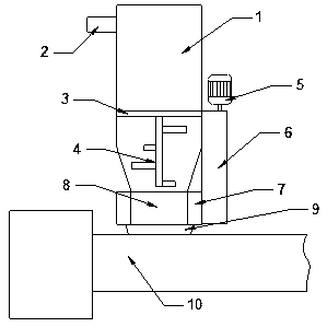
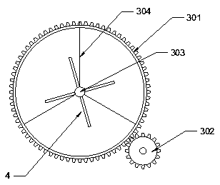
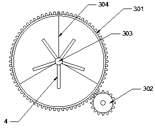
[0027] Depend on figure 1 , figure 2 , Figure 4 ~ Figure 6 As shown, an automatic feeding machine includes a storage tank 1, a feeding port 2, a rotating disk 3, a stirring paddle 4, a motor 5, a transmission device 6, a longitudinal propulsion device 7, a feeding port 8, and a feeding port 9 and an extruder 10, the storage barrel 1 is installed above the extruder 10 with a feed port 9, the top of the storage barrel 1 is provided with a feed port 2, and the bottom of the storage barrel 1 is provided with a discharge port 8 , the rotating disk 3 is located inside the storage tank 1, the rotating disk 3 is composed of an outer gear ring 301, a driving wheel 302, an inner shaft 303 and a connecting rod 304, the outer gear ring 301 is connected with the inner shaft 303 through the connecting rod 304, and the stirring paddle 4 is connected with the inner shaft 303;
[0028] The longitudinal propulsion device 7 includes a propulsion screw I11, a propulsion screw II12, a propuls...
Embodiment 2
[0033] Depend on figure 1 , Figure 3 ~ Figure 6 As shown, an automatic feeding machine includes a storage tank 1, a feeding port 2, a rotating disk 3, a stirring paddle 4, a motor 5, a transmission device 6, a longitudinal propulsion device 7, a feeding port 8, and a feeding port 9 and an extruder 10, the storage barrel 1 is installed above the extruder 10 with a feed port 9, the top of the storage barrel 1 is provided with a feed port 2, and the bottom of the storage barrel 1 is provided with a discharge port 8 , the rotating disk 3 is located inside the storage tank 1, the rotating disk 3 is composed of an outer gear ring 301, a driving wheel 302, an inner shaft 303 and a connecting rod 304, the outer gear ring 301 is connected with the inner shaft 303 through the connecting rod 304, and the stirring paddle 4 is connected with the inner shaft 303;
[0034] The longitudinal propulsion device 7 includes a propulsion screw I11, a propulsion screw II12, a propulsion screw III...
Embodiment 3
[0039] Depend on figure 1 , Figure 3 ~ Figure 5 , Figure 7 As shown, an automatic feeding machine includes a storage tank 1, a feeding port 2, a rotating disk 3, a stirring paddle 4, a motor 5, a transmission device 6, a longitudinal propulsion device 7, a feeding port 8, and a feeding port 9 And the extruder 10, the storage barrel 1 with the feed port 2 is installed above the extruder 10 with the feed port 9, the inside of the storage barrel 1 is provided with a rotating disk 3, and the rotating disk 3 is formed from the outside The gear ring 301, the driving wheel 302, the inner shaft 303 and the connecting rod 304 are composed, the outer gear ring 301 is connected with the inner shaft 303 through the connecting rod 304, and the stirring paddle 4 is connected with the inner shaft 303;
[0040]The longitudinal propulsion device 7 includes a propulsion screw I11, a propulsion screw II12, a propulsion screw III13 and a drive gearbox, which are distributed on the outer wall ...
PUM
 Abstract
Description
Claims
Application Information
 - R&D Engineer
- R&D Manager
- IP Professional
- Industry Leading Data Capabilities
- Powerful AI technology
- Patent DNA Extraction
Browse by: Latest US Patents, China's latest patents, Technical Efficacy Thesaurus, Application Domain, Technology Topic, Popular Technical Reports.
© 2024 PatSnap. All rights reserved.Legal|Privacy policy|Modern Slavery Act Transparency Statement|Sitemap|About US| Contact US: help@patsnap.com