
Trash rack with trash cleaning grab bucket

A trash rack and pollution cleaning technology, which is applied in the direction of general water supply conservation, cleaning of open water surfaces, water conservancy projects, etc., can solve the problems of not being able to effectively provide cleaning at the bottom of the trash rack, and achieve compact structure, low cost, and high cleaning efficiency high effect

Pending Publication Date: 2019-07-12
SHANGHAI WATER ENG DESIGN & RES INST
View PDF1 Cites 4 Cited by
  • Summary
  • Abstract
  • Description
  • Claims
  • Application Information

AI Technical Summary

Problems solved by technology

[0004] At present, there is a Chinese patent application publication number CN107780397A which discloses a simple cleaning machine for trash racks. This patent cleans up and down by lifting the cleaning bucket, but this patent cannot effectively provide cleaning of the bottom of the trash rack. There is a problem of how to effectively clean the bottom of the trash rack

Method used


Image

  • Trash rack with trash cleaning grab bucket
  • Trash rack with trash cleaning grab bucket
  • Trash rack with trash cleaning grab bucket

Examples


Embodiment 1

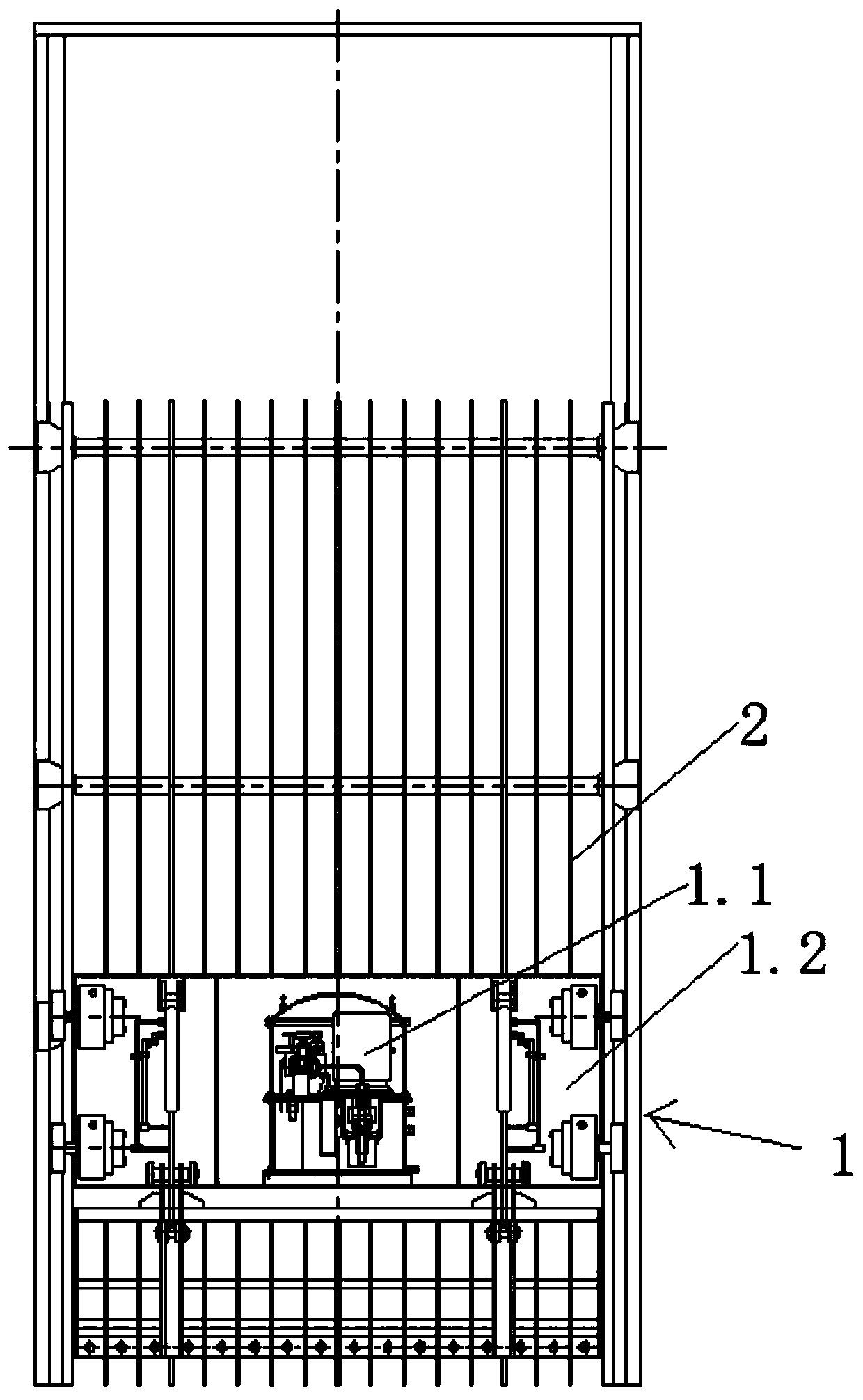
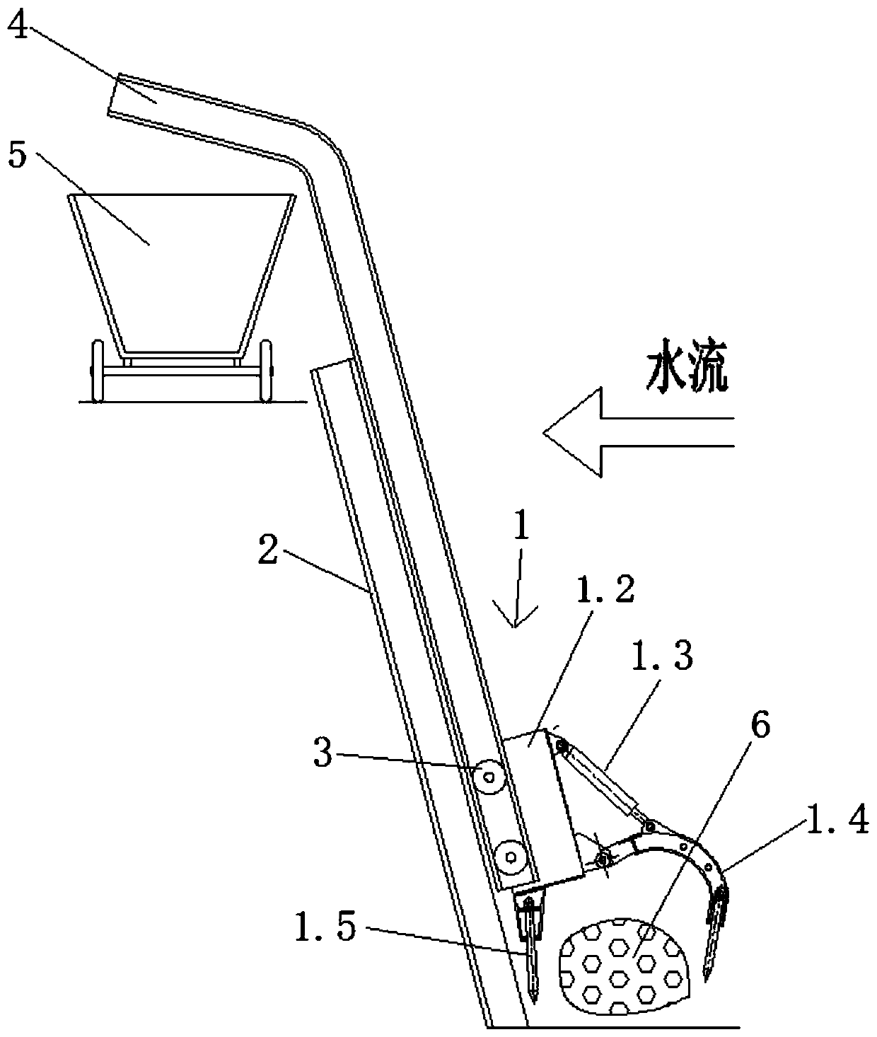
[0026] see Figure 1 to Figure 2 A trash rack with a trash rack as shown includes a trash rack 2 and a trash rack device 1 arranged on the trash rack 2, such as Figure 5 to Figure 6 The cleaning grab device 1 shown includes a cleaning grab 1.2 arranged on the trash rack 2. The bottom of the cleaning grab 1.2 is provided with shovel teeth 1.5, and the cleaning grab 1.2 is also provided with rotating teeth 1.4. And the rotating drive device that drives rotary gear 1.4 to rotate. The rotary driving device in this embodiment includes a hydraulic cylinder 1.3 connected to the rotary gear 1.4 and a hydraulic system 1.1 for driving the hydraulic cylinder 1.3 to work.

[0027] The rotating gear 1.4 has an arc-shaped structure as a whole. One end of the rotating gear 1.4 is hinged on the cleaning bucket 1.2. The other end of the rotating gear 1.4 is used to grab the dirt 6 at the bottom of the trash rack. One end of the hydraulic cylinder 1.3 is hinged on the cleaning bucket. On the...

Embodiment 2

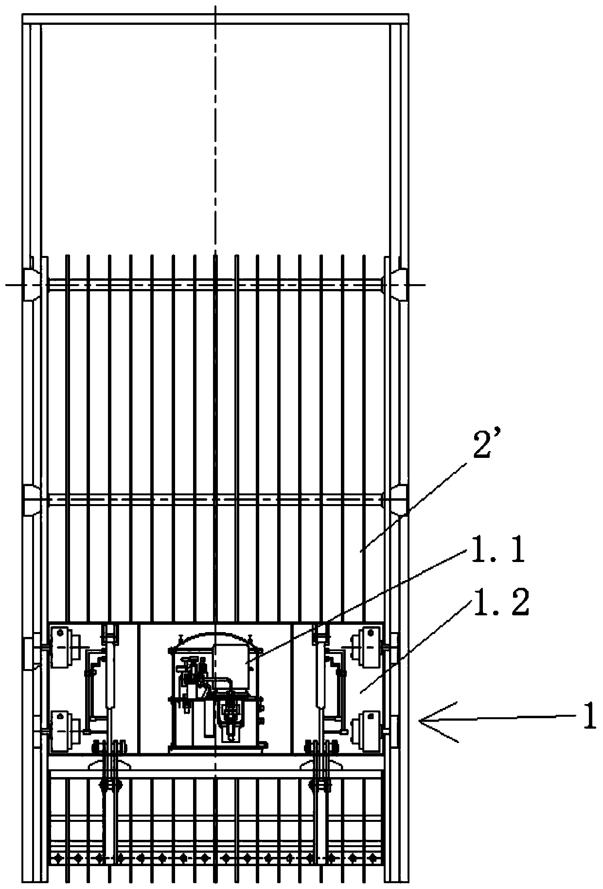
[0033] see Figure 3 to Figure 4 Shown a kind of trash rack with cleaning bucket, including trash rack 2 ' and being arranged on trash rack 2 ', the cleaning grab bucket set 1, as Figure 5 to Figure 6 The cleaning grab device 1 shown includes a cleaning grab 1.2 that is arranged up and down on the trash rack 2'. The bottom of the cleaning grab 1.2 is provided with shovel teeth 1.5, and the cleaning grab 1.2 is also provided with rotating teeth. 1.4 and the rotary driving device that drives rotary gear 1.4 to rotate. The rotary driving device in this embodiment includes a hydraulic cylinder 1.3 connected to the rotary gear 1.4 and a hydraulic system 1.1 for driving the hydraulic cylinder 1.3 to work.

[0034] The rotating gear 1.4 has an arc-shaped structure as a whole. One end of the rotating gear 1.4 is hinged on the cleaning bucket 1.2. The other end of the rotating gear 1.4 is used to grab the dirt 6 at the bottom of the trash rack. One end of the hydraulic cylinder 1.3 i...


PUM


Abstract

The invention discloses a trash rack with a trash cleaning grab bucket. The trash rack with the trash cleaning grab bucket includes a trash rack body and a trash cleaning grab bucket device arranged on the trash rack body, the trash cleaning grab bucket device includes the trash cleaning grab bucket arranged on the trash rack body in a lifting mode, shovel teeth are arranged at the bottom of the trash cleaning grab bucket, and rotating teeth and a rotation driving device for driving the rotating teeth to rotate are further arranged on the trash cleaning grab bucket. The trash rack with the trash cleaning grab bucket has the characteristics that the cost is low, the trash cleaning efficiency is high and the structure is compact, the cleaning problems of branches, trunks and stones before the trash rack can be solved, and the cleaning problem of dead corner areas before the trash rack can be further solved.

Description

technical field [0001] The invention relates to a device for intercepting dirt at the water inlet of a water turbine of a hydropower station or at the inlet of a pump station, in particular to a trash rack with a dirt-cleaning grab bucket. Background technique [0002] The trash rack is generally arranged in front of the water inlet of the hydroelectric generating unit or pumping station of the hydropower station to intercept the dirt to ensure the safety of the operation of the hydroelectric generating unit or the cleanness of the pumping water in the pumping station. Generally, a lot of dirt will accumulate in front of the trash rack, which will affect the water flow of the trash rack and threaten the safe operation of the trash rack in severe cases. [0003] At present, there are two commonly used ways to clean the trash rack. One is to use a rotary trash rack to remove the dirt attached to the front of the trash rack and to the surface of the trash rack, and the other is...

Claims


Application Information

Patent Timeline
Patent Type & Authority Applications(China)
IPC IPC(8): E02B15/06E02B15/10
CPCE02B15/06E02B15/10Y02A20/204
Inventor 田盈辉董永霞朱焱峰王鹏展黄伟董国睿唐杰何山青
Owner SHANGHAI WATER ENG DESIGN & RES INST
Learn More