
Magnetic suspension shock absorber

A shock absorber, magnetic suspension technology, applied in the direction of spring/shock absorber, magnetic spring, spring, etc., can solve the problems of high cost, shock absorber failure, limited application of spring shock absorber, etc. The effect of low precision requirements and reduced manufacturing costs

Inactive Publication Date: 2019-07-12
速德实业股份有限公司
View PDF9 Cites 1 Cited by
  • Summary
  • Abstract
  • Description
  • Claims
  • Application Information

AI Technical Summary

Problems solved by technology

[0002] The current shock absorbers mainly include spring shock absorbers and pneumatic shock absorbers. Among them, the support force of spring shock absorbers is relatively small, so the application occasions of spring shock absorbers are limited, and the number of uses of springs will reach After a certain degree, metal fatigue occurs and fails; while the pneumatic shock absorber needs to be filled with liquid nitrogen at low temperature and converted into high-pressure gas at room temperature, and the cylinder and piston used have high processing precision, complicated production and high cost. In addition, pneumatic shock absorbers are also dangerous in high-temperature environments. After a long time of use, high-pressure gas leakage will occur due to the aging of the seals, which will cause the shock absorbers to fail; in addition to the above two types of shock absorbers, there is another A hydraulic shock absorber is driven by liquid, so the structure of the liquid shock absorber is more complicated, and the hydraulic shock absorber is characterized by strong support, but slow movement, and the application occasion is also different from the above two shock absorbers. Shock absorbers are not the same, in view of this, after observing the above-mentioned shortcoming, the creator of this case thinks that the known shock absorbers really need further improvement, and the present invention produces one by one

Method used


Image

  • Magnetic suspension shock absorber
  • Magnetic suspension shock absorber
  • Magnetic suspension shock absorber

Examples


Embodiment Construction

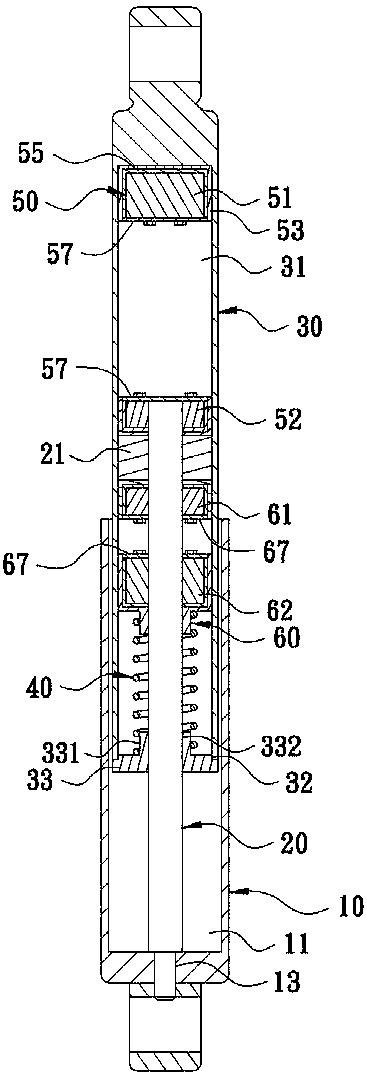
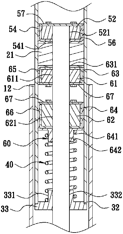
[0020] Please see first Figure 1 to Figure 3 As shown, it discloses a magnetic suspension shock absorber, which includes:

[0021] An outer casing 10, which is in the shape of a hollow cylinder, has a container 11 in the outer casing 10, and one end of the outer casing 10 is provided with an opening 12, and the opening 12 communicates with the container 11, and the outer casing 10 The other end is provided with a through hole 13 .

[0022] One end of a shaft 20 is disposed in the through hole 13 of the outer cylinder 10 , and the other end of the shaft 20 is disposed in the cavity 11 of the outer cylinder 10 , passes through the opening 12 , and is provided with a piston 21 .

[0023] An inner sleeve cylinder 30, which is arranged on the shaft rod 20, and is slidably arranged in the housing groove 11 of the outer sleeve cylinder 10, and the inner sleeve cylinder 30 is hollow and long cylindrical corresponding to the outer sleeve cylinder 10, the inner sleeve cylinder 30 The...


PUM


Abstract

The invention discloses a magnetic suspension shock absorber. The magnetic suspension shock absorber is mainly composed of an outer sleeve cylinder, a shaft rod, an inner sleeve cylinder and two groups of magnetic suspension units, wherein each group of magnetic suspension units is provided with two magnets, the corresponding surfaces the two magnets of the each group of magnetic suspension unitshave same magnetism and are separately arranged on the shaft rod and the inner sleeve cylinder, therefore, when the inner sleeve cylinder is impacted by external force, the two magnets of one of the group of magnetic suspension units are close mutually to generate the action of homopolar repulsion, and thus, the effects of buffering and shock absorbing are achieved.

Description

technical field [0001] The present invention relates to a shock absorber, in particular to a magnetic suspension shock absorber. Background technique [0002] The current shock absorbers mainly include spring shock absorbers and pneumatic shock absorbers. Among them, the support force of spring shock absorbers is relatively small, so the application occasions of spring shock absorbers are limited, and the number of uses of springs will reach After a certain degree, metal fatigue occurs and fails; while the pneumatic shock absorber needs to be filled with liquid nitrogen at low temperature and converted into high-pressure gas at room temperature, and the cylinder and piston used have high processing precision, complicated production and high cost. In addition, pneumatic shock absorbers are also dangerous in high-temperature environments. After a long time of use, high-pressure gas leakage will occur due to the aging of the seals, which will cause the shock absorbers to fail; ...

Claims


Application Information

Patent Timeline
Patent Type & Authority Applications(China)
IPC IPC(8): F16F6/00
CPCF16F6/005
Inventor 卜德贵刘家庆
Owner 速德实业股份有限公司
Learn More