An optical flow sensor integrating cameras with different focal lengths

A technology of optical flow sensor and ranging sensor, which is applied in the field of optical flow sensor, can solve the problems of limiting the height, direction and range of motion of rotor drones, and achieve the effect of improving accuracy and reducing small speed errors

Active Publication Date: 2021-02-09
SHANGHAI JIAO TONG UNIV
View PDF11 Cites 0 Cited by
  • Summary
  • Abstract
  • Description
  • Claims
  • Application Information

AI Technical Summary

Problems solved by technology

[0004] At present, the existing optical flow sensors all use a camera with a single focal length. When the ground texture is small or has a high degree of repetition (such as common wooden floors, tiles, asphalt roads, etc.), the camera of the rotor drone can only be used in a very small area. The texture captured in a narrow height range can achieve a clear, reasonable range, and be used for the calculation of the optical flow velocity of the UAV movement, which greatly limits the height direction and activity range of the rotor UAV

Method used


Image

  • An optical flow sensor integrating cameras with different focal lengths
  • An optical flow sensor integrating cameras with different focal lengths
  • An optical flow sensor integrating cameras with different focal lengths

Examples


Embodiment 1

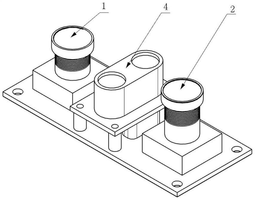
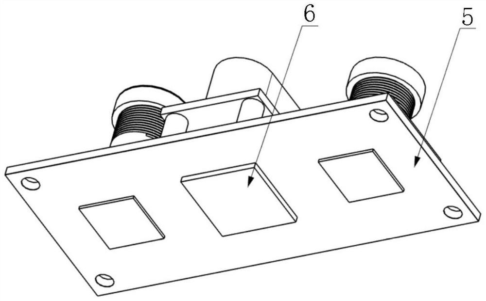
[0035] Such as figure 1 and figure 2 As shown, an optical flow sensor integrating cameras with different focal lengths provided by the present invention includes a camera 1 with a focal length of 2.8mm (the full-frame equivalent focal length is about 20mm), and a camera 2 with a focal length of 8.0mm (the full-frame equivalent focal length is about 20mm). The focal length is about 57 mm), the distance measuring sensor 4, the circuit board 5, and the embedded chip 6; wherein, the distance measuring sensor 4, the camera 1 with a focal length of 2.8 mm, and the camera 2 with a focal length of 8.0 mm are arranged on the top of the circuit board 5 On the side, the embedded chip 6 is arranged on the bottom side of the circuit board 5, and the embedded chip 6 is respectively connected to the distance measuring sensor 4, the camera 1 with a focal length of 2.8 mm, and the camera 2 with a focal length of 8.0 mm.

[0036]Camera 1 with a focal length of 2.8mm and camera 2 with a focal ...

Embodiment 2

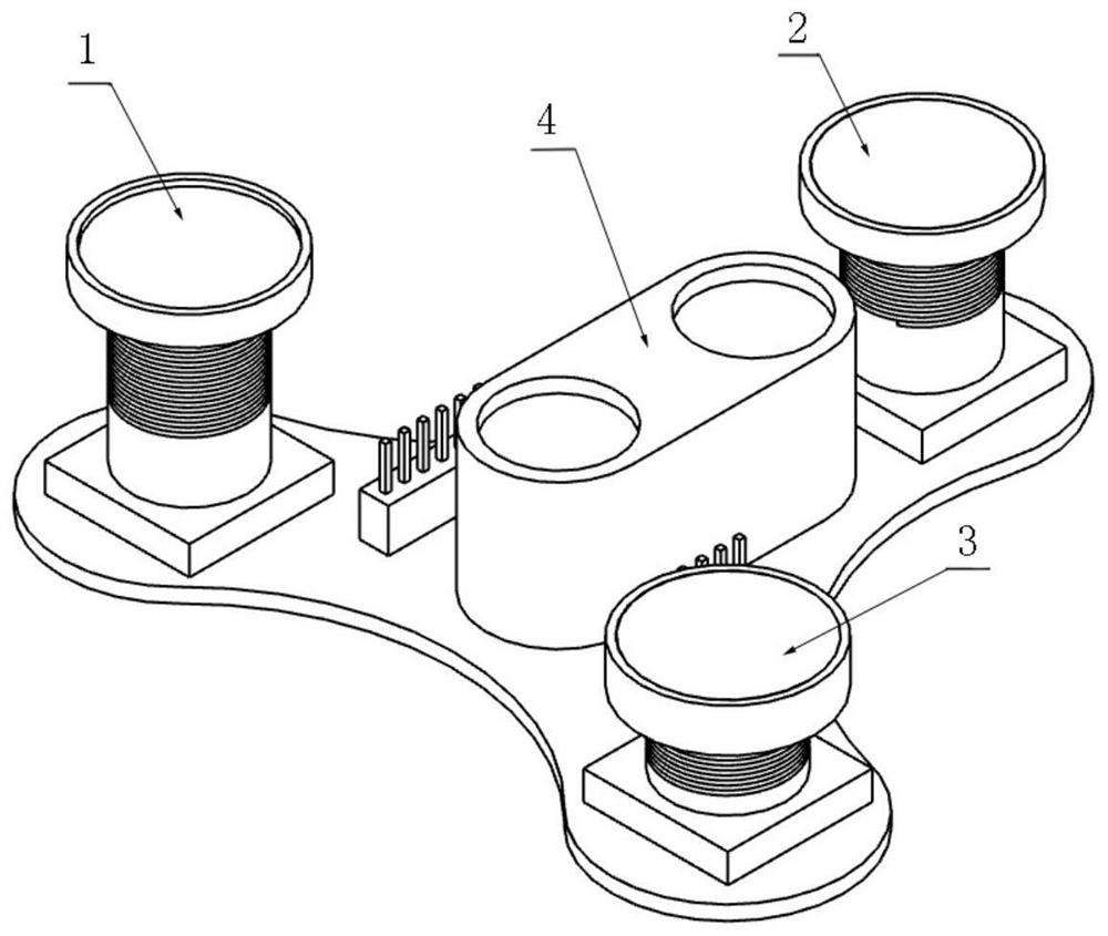
[0040] On the basis of Embodiment 1, in this embodiment, a camera 1 with a focal length of 2.8 mm, a camera 2 with a focal length of 8.0 mm, and a camera 3 with a focal length of 16.0 mm (the full-frame equivalent focal length is about 114 mm respectively), wherein, The reasonable use height range of the images collected by camera 3 with a focal length of 16.0mm is 2.5m-8.0m; camera 1, camera 2 and camera 3 have a range of 0.2m and 0.5m from 1.0m to 1.2m, 2.5m to 3.0m, respectively. Overlapping working ranges. By adding the camera 3 with a focal length of 16.0mm, the working range of the optical flow sensor to obtain images with clear texture and moderate picture range is greatly improved, and the positioning of the rotor UAV in a larger plane moving space is realized.


PUM


Abstract

The invention discloses an optical flow sensor integrating cameras with different focal lengths, which relates to the field of visual positioning sensor design for rotor drones, including a circuit board, a ranging sensor, an embedded chip, and a camera; wherein, the ranging sensor and the The camera is configured on one side of the circuit board; the embedded chip is configured on the other side of the circuit board, and the embedded chip is respectively connected with the distance measuring sensor and the camera. The present invention adopts a plurality of fixed-focus cameras to increase the zoom speed and meet the rapidity requirements of optical flow. When it is in a wide range of different heights, it improves the definition of the ground texture picture used for estimating the optical flow speed, and through the optical flow The method can accurately obtain the actual movement speed of the rotor UAV, thereby improving the overall computing efficiency.

Description

technical field [0001] The invention relates to the field of design of visual positioning sensors for rotor drones, in particular to an optical flow sensor integrating cameras with different focal lengths. Background technique [0002] The optical flow sensor is a sensor that performs image processing based on the optical flow method in computer vision and is used to estimate the motion speed of itself or the installed object. It has the advantages of low cost and fast calculation speed. The optical flow method is divided into two steps to estimate the speed. The first step is to match the pixel brightness or feature points between two adjacent frames of images captured by the camera, and estimate its moving distance on the image according to the time between two frames to obtain a two-dimensional instantaneous Image moving velocity field, when the image is a flat fixed object (such as the ground), the velocity distribution in the velocity field is consistent and has a corre...

Claims


Application Information

Patent Timeline
Patent Type & Authority Patents(China)
IPC IPC(8): G01P3/38
CPCG01P3/38
Inventor 陈刚董伟盛鑫军朱向阳
Owner SHANGHAI JIAO TONG UNIV
Why Eureka
Try Eureka