Dual-optical-path optical current sensor

A current sensor, dual optical path technology, applied in the direction of only measuring current, measuring current/voltage, instruments, etc., can solve the problems of inability to accurately measure the DC component or aperiodic component of the current, declination deviation, etc., to improve the measurement stability and reliability. The effect of measuring accuracy

Active Publication Date: 2019-07-12
HARBIN INST OF TECH +2
View PDF8 Cites 3 Cited by
  • Summary
  • Abstract
  • Description
  • Claims
  • Application Information

AI Technical Summary

Problems solved by technology

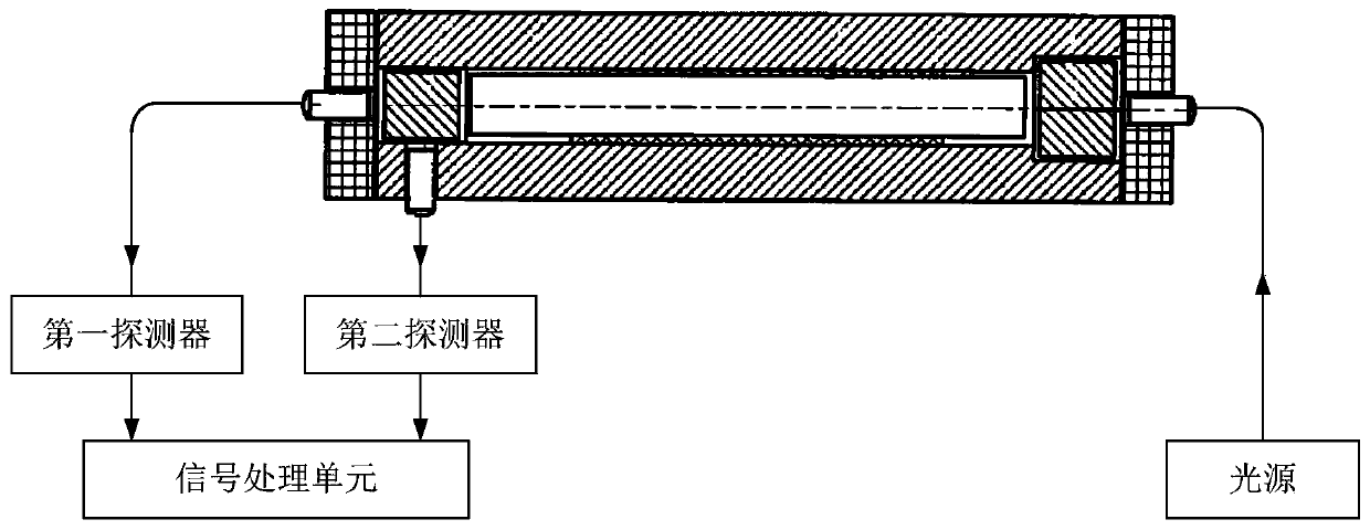
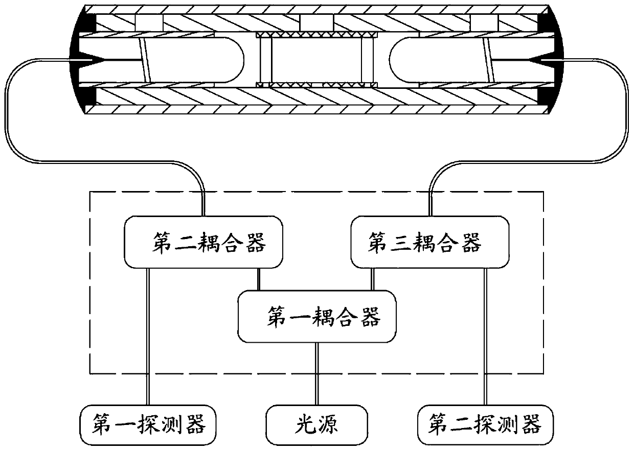
[0030] The present invention is to solve the problem that the existing optical current sensor cannot accurately measure the current DC component or the non-peri

Method used


Image

  • Dual-optical-path optical current sensor
  • Dual-optical-path optical current sensor
  • Dual-optical-path optical current sensor

Examples


specific Embodiment approach 1

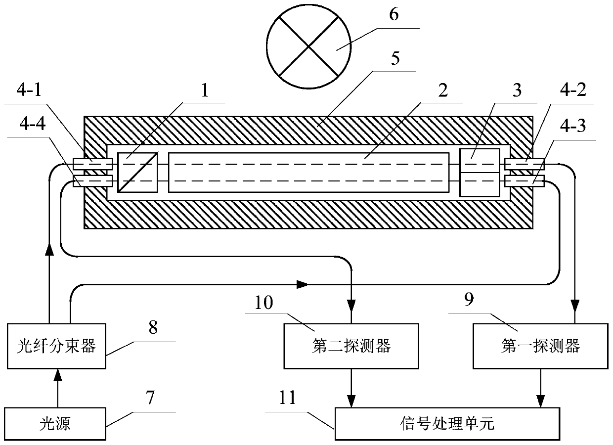
[0059] Specific implementation mode one: refer to figure 1 This embodiment is specifically described. The dual optical path optical current sensor described in this embodiment includes: a first polarizing beam splitting prism 1, a magneto-optic glass beam 2, a second polarizing beam splitting prism 3, a first fiber collimator 4-1, a second polarizing beam splitting prism Second fiber collimator 4-2, third fiber collimator 4-3, fourth fiber collimator 4-4, metal substrate 5, fiber beam splitter 8, first detector 9, second detector 10 And signal processing unit 11.

[0060] The first polarizing beam-splitting prism 1 and the second polarizing beam-splitting prism 3 are respectively located at the two ends of the magneto-optic glass beam 2, and the angle between the transmission axis of the first polarization beam-splitting prism 1 and the transmission axis of the second polarization beam-splitting prism 3 is 45° °, the first fiber collimator 4-1 and the fourth fiber collimator...


PUM


Abstract

A double-optical-path optical current sensor relates to the field of current measurement. The invention aims to solve the problem that the current direct-current component or the non-periodic component cannot be accurately measured due to linear birefringence and incident declination deviation of the existing optical current sensor. Light output by a light source is divided into two light beams through an optical fiber beam splitter, and one light beam sequentially passes through a first optical fiber collimator, a first polarization splitting prism, a magneto-optical glass light beam, a second polarization splitting prism and a second optical fiber collimator to be incident to a first detector; the other beam of light sequentially passes through a third optical fiber collimator, a secondpolarization splitting prism, a magneto-optical glass light beam, a first polarization splitting prism and a fourth optical fiber collimator and is incident to a second detector; and the electric signal output end of the first detector and the electric signal output end of the second detector are simultaneously connected with the electric signal input end of the signal processing unit. The methodis used for accurately measuring the direct current component or the non-periodic component.

Description

technical field [0001] The invention belongs to the field of current measurement in electric power system. Background technique [0002] Optical current transformers measure current based on the Faraday magneto-optical effect principle, which is essentially the integration of the magnetic field along the sensing optical path. Because of its excellent performance and potential advantages, it has become the main direction of current transformer development. Compared with the all-optical current transformer, the magneto-optic glass optical current transformer has the advantages of simple structure, less optical components, good stability and low cost, and is an ideal optical current transformer. [0003] In the use of optical current transformers, the measured current information is generally obtained by detecting the size of the Faraday rotation angle. The signal processing methods used mainly include a single optical path scheme and a double detector subtraction and sum schem...

Claims


Application Information

Patent Timeline
IPC IPC(8): G01R19/00
CPCG01R19/0092
Inventor 于文斌张国庆郭志忠王贵忠李洪波侯英伟
Owner HARBIN INST OF TECH
Why Eureka
Try Eureka