Laser radar system and control method thereof

A laser radar and laser technology, applied in the field of laser radar system and its control, can solve the problems of affecting the ranging ability of laser radar and large interference of echo signals.

Active Publication Date: 2019-07-12
SUTENG INNOVATION TECH CO LTD
View PDF13 Cites 10 Cited by
  • Summary
  • Abstract
  • Description
  • Claims
  • Application Information

AI Technical Summary

Problems solved by technology

[0004] However, in the off-axis scheme, when the background light is strong, the optical information received by the receiving device contains not only the echo signal but also a large amount of background light. Ranging capability

Method used


Image

  • Laser radar system and control method thereof
  • Laser radar system and control method thereof
  • Laser radar system and control method thereof

Examples


Embodiment Construction

[0031] In order to make the purpose, technical solution and advantages of the present application clearer, the present application will be further described in detail below in conjunction with the accompanying drawings and embodiments. It should be understood that the specific embodiments described here are only used to explain the present application, and are not intended to limit the present application.

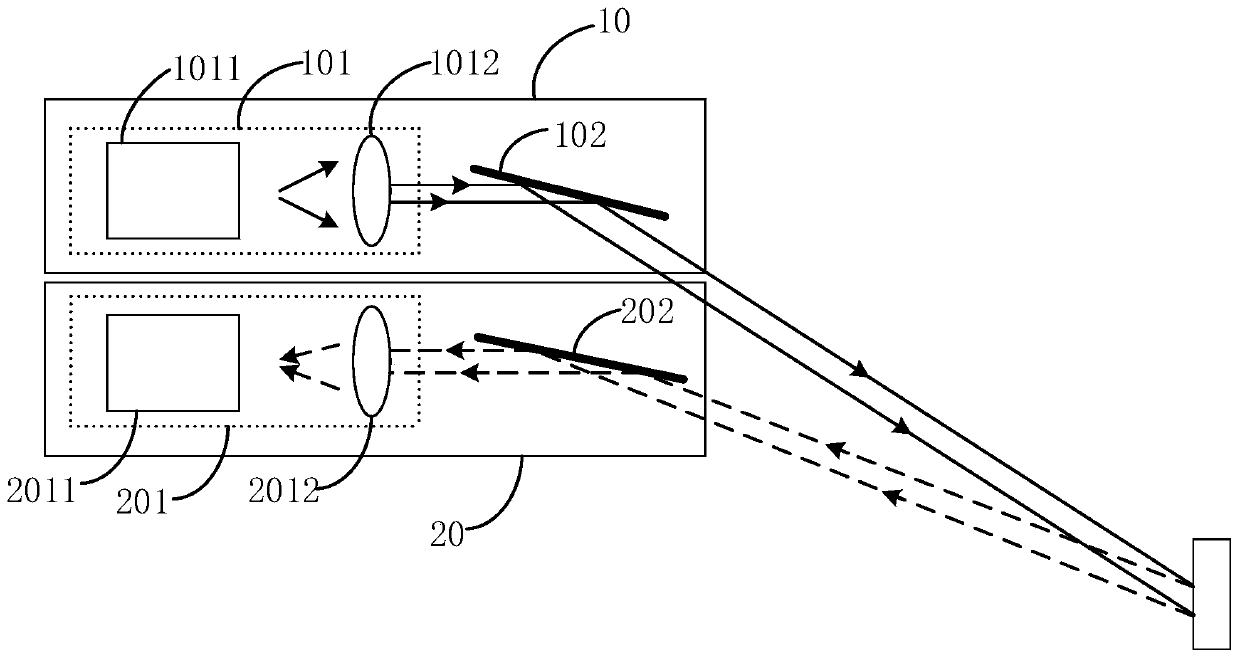
[0032] refer to figure 1 , shows a lidar system provided by an embodiment of the present invention. The lidar system includes a transmitting device 10 and a receiving device 20 with an optical path off-axis; the transmitting device 10 includes a laser transmitter 101 and a first vibrating mirror 102, and the receiving device 20 includes a laser receiver 201 and a second vibrating mirror 202;

[0033] The first vibrating mirror 102 is used to reflect the outgoing light beam output by the laser transmitter 101 to the target object;

[0034] The second vibrating mirror 202 ...


PUM


Abstract

The invention relates to a laser radar system and a control method thereof. The laser radar system comprises a transmitting device and a receiving device, wherein the transmitting device comprises a laser transmitter and a first galvanometer, and the receiving device comprises a laser receiver and a second galvanometer; the first galvanometer is used for reflecting the emergent light beam output by the laser transmitter to a target object; and the second galvanometer is used for receiving the echo light beam and reflecting the received echo light beam to the laser receiver. According to the embodiment of the invention, the interference of the background light to the echo light beam can be reduced, so that the laser radar system can easily identify the effective light information in the light information, thereby improving the distance measurement capability of the laser radar; the transmitting device and the receiving device are arranged in an off-axis mode, installation and adjustmentare easy, and preamble interference is avoided. Meanwhile, all echo light beams can be received through the second galvanometer, the energy utilization rate of the echo light beams is high, and the detection capacity is improved.

Description

technical field [0001] The present application relates to the technical field of radar, in particular to a laser radar system and a control method thereof. Background technique [0002] Lidar mainly includes off-axis solutions and coaxial solutions. In the coaxial scheme, the transmitting optical path and the receiving optical path are in the same path, and the field of view angles of the transmitting device and the receiving device are basically the same; at the same time, in order to make the receiving optical path and the transmitting optical path split and be received by the detector, a spectroscope is usually used for splitting the light. Receiving the S light in the echo beam will affect the detection ability. [0003] Compared with the coaxial solution, the off-axis solution has the advantages of: the transmitting device and the receiving device are separated, and the stray light in the system is relatively small; moreover, the structure is simple, the installation a...

Claims


Application Information

Patent Timeline
Patent Type & Authority Applications(China)
IPC IPC(8): G01S17/88G01S17/93G01S7/493G01S7/487G01S7/481
CPCG01S17/88G01S7/481G01S7/487G01S7/493G01S17/931
Inventor 罗斯特刘夏王吉魏威李兴华
Owner SUTENG INNOVATION TECH CO LTD
Why Eureka
Try Eureka