
Multi-line laser radar

A multi-line laser and radar technology, applied in the field of laser detection, can solve the problems of complicated installation and adjustment process, increased volume, unfavorable production and mass production, etc.

Active Publication Date: 2020-06-26
北京大汉正源科技有限公司
View PDF5 Cites 4 Cited by
  • Summary
  • Abstract
  • Description
  • Claims
  • Application Information

AI Technical Summary

Problems solved by technology

[0003] The current 3D scanning lidar mostly adopts the multi-line scanning method, that is, multiple laser tubes are used to emit sequentially, and the structure is that multiple laser tubes are arranged vertically. receiving detectors to ensure that each receiving detector corresponds to the field of view angle of the emitting laser tube. Therefore, the installation and adjustment process is very complicated, which is not conducive to production and mass production. At the same time, because multiple receiving detectors and transmitting units The stacking makes the volume of the lidar with a higher number of lines doubled, and since each detector has the same size, how to make the point cloud information more dense in the central area in the vertical direction is also the current multi-line lidar intractable problem

Method used


Image

  • Multi-line laser radar
  • Multi-line laser radar
  • Multi-line laser radar

Examples


specific Embodiment

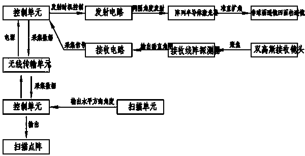
[0034] Such as figure 1 As shown, a multi-line laser radar includes a control unit, a transmitting unit connected to the control unit, a receiving unit, a scanning unit, a wireless transmission unit, and a power supply unit;

[0035] The control unit includes an FPGA, which controls the transmitting unit to transmit by receiving the trigger signals of the scanning unit at different angles, and then amplifies the received echo through the receiving unit after it is irradiated on the detection object, and then performs timing and distance measurement on the logic level signal , and calculate the reflectivity intensity according to the width of the level signal, and the control unit combines the angle information in the horizontal and vertical directions and the distance information to obtain a three-dimensional point cloud;

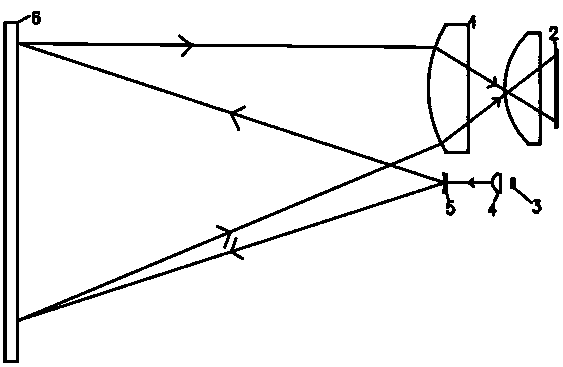
[0036] The emitting unit includes an emitting circuit board, an array semiconductor laser, an aspheric lens, and a concave cylindrical mirror; the emitting...


PUM


Abstract

The invention discloses multi-line laser radar, which comprises a control unit, and a transmitting unit, a receiving unit, a scanning unit, a wireless transmission unit and a power supply unit which are connected with the control unit. The control unit controls the transmitting unit to transmit by receiving trigger signals of the scanning unit at different angles; after the light irradiates a detected object, echo amplification is received through the receiving unit, then timing ranging is conducted on logic level signals, meanwhile, the reflectivity intensity is calculated according to the width of the level signals, and the control unit obtains three-dimensional point cloud in combination with angle information and distance information in the horizontal direction and the vertical direction. According to the invention, the characteristics of a plurality of pixels of an array detector are utilized, angle information is obtained through pixel positions, the array detector uses non-uniform micro-element size arrangement to obtain high-density central area test point clouds, and when the array detector is matched with a receiving lens, the lengths of the two ends of the detector are increased along with edge distortion, so that the uniformity of a receiving angle is facilitated.

Description

technical field [0001] The patent of the present invention relates to the technical field of laser detection, in particular to a multi-line laser radar. Background technique [0002] Laser scanning ranging radar can be used to detect the position, contour and speed of the target. The application field of laser ranging radar is gradually expanding, accurate measurement, navigation and positioning, safe obstacle avoidance, and it is beginning to be applied to unmanned driving technology. Laser scanning radar is the The emitted laser beam forms a scanning section through scanning emission, so as to test the characteristic information of the object to be tested. At present, the 3D scanning lidar is multi-layer scanning in the vertical direction, which can well reflect the characteristic information of the object to be measured, and is suitable for many fields, such as unmanned navigation and shape contour detection. [0003] The current 3D scanning lidar mostly adopts the multi...

Claims


Application Information

Patent Timeline
IPC IPC(8): G01S7/481
CPCG01S7/4816G01S7/4817
Inventor 刘定
Owner 北京大汉正源科技有限公司
Learn More