
Circuit control type oven

A circuit control and oven technology, applied in the field of ovens, can solve problems such as high cost and complex structure, and achieve the effects of low cost, simple circuit structure, and preventing food from being scorched and burnt.

Pending Publication Date: 2019-07-12
CHINABEST HOME APPLIANCE
View PDF0 Cites 3 Cited by
  • Summary
  • Abstract
  • Description
  • Claims
  • Application Information

AI Technical Summary

Problems solved by technology

[0002] In a traditional oven, there are heating components inside to heat the heating cavity, so as to bake the food inside. In the past, the same control logic was used for the heating components in different positions, for example, the temperature detection component was used to control the temperature of the heating cavity. The heating temperature is detected. If the temperature of the heating inner cavity reaches a certain threshold, all heating components are controlled to be turned off at the same time. However, in fact, the food is generally placed on the baking tray in the heating inner cavity. If the temperature of the heating element is too high, the food will be scorched, while other heating elements that heat the top or side of the heating cavity will not damage the quality of the food even if the heating temperature exceeds the originally set temperature threshold. Even to some extent, it is conducive to baking with a better taste, while the previous ovens did not separately control the heating components in different positions, and if it needs to be improved, the structure is more complicated and the cost is relatively high

Method used


Image

  • Circuit control type oven
  • Circuit control type oven
  • Circuit control type oven

Examples


Embodiment Construction

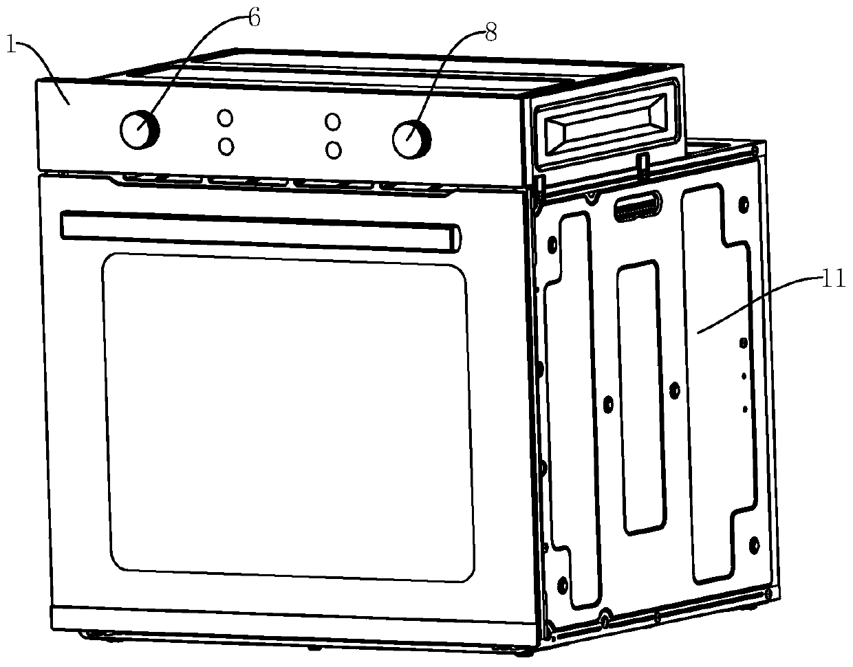
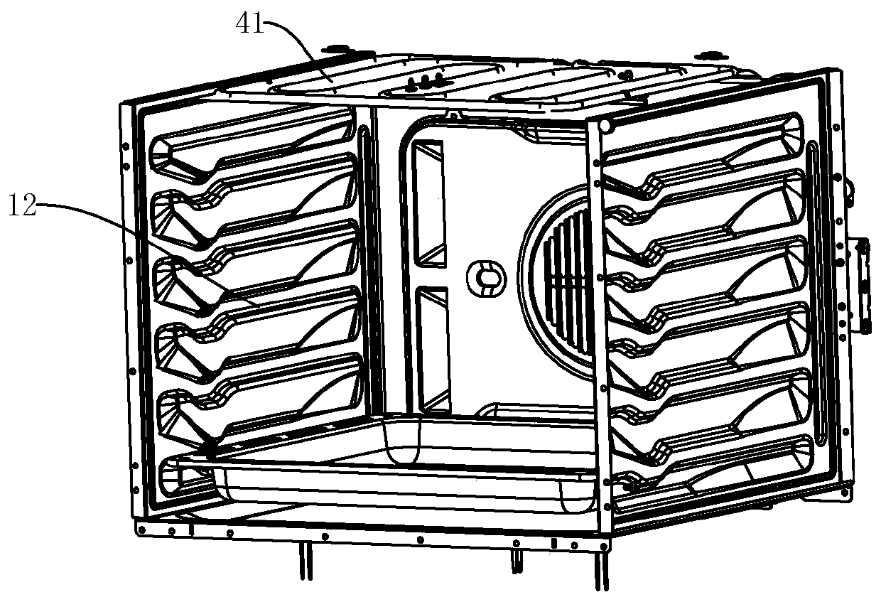
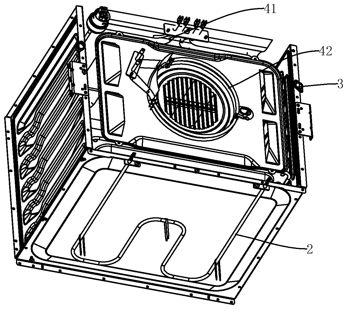
[0029] Such as Figure 1-Figure 6 As shown, a circuit-controlled oven includes an oven body 1;

[0030] The first heating component 2 is arranged at the bottom of the oven body 1;

[0031] The second heating component 4 is arranged on the top or side of the oven body 1;

[0032] The first power supply branch and the second power supply branch are connected in parallel, the first heating component 2 is connected in series in the first power supply branch, and the second heating component 4 is connected in series in the second power supply branch;

[0033] The first temperature control switch assembly 3 is arranged on the oven body 1 to detect the heating temperature, the first temperature control switch assembly 3 is connected in series in the first power supply branch, and the first temperature control switch assembly 3 is provided with a first temperature threshold, When the heating temperature exceeds the first temperature threshold, the first temperature control switch assembly 3 i...


PUM


Abstract

The invention discloses a circuit control type oven. The oven comprises an oven body, a first heating assembly arranged at the bottom of the oven body, a second heating assembly arranged on the top orthe side face of the oven body, a first power supply branch circuit, a second power supply branch circuit and a first temperature control switch assembly, wherein the first power supply branch circuit and the second power supply branch circuit are connected in parallel, the first heating assembly is connected in series with the first power supply branch circuit, and the second heating assembly isconnected in series with the second power supply branch circuit. The first temperature control switch assembly is arranged on the oven body to detect the heating temperature, the first temperature control switch assembly is connected to the first power supply branch circuit in series, a first temperature threshold value is arranged in the first temperature control switch assembly, and when the heating temperature exceeds the first temperature threshold value, the first temperature control switch assembly is disconnected. According to the design, a simple circuit structure is adopted, cost islow, independent control over heating parts at different positions is achieved, and the baking quality is improved.

Description

Technical field [0001] The present invention relates to ovens. Background technique [0002] Traditional ovens are equipped with heating components inside to heat the heating cavity so as to bake the food inside. In the past, the same control logic was used for heating components at different locations. For example, a temperature detection component was used to control the heating cavity. The heating temperature is detected. If the temperature of the heating cavity reaches a certain threshold, each heating component is controlled to turn off at the same time. However, in fact, food is generally placed on a baking tray in the heating cavity, and the bottom of the heating cavity is If the temperature of the heating component is too high, the food will be scorched, while other heating components that heat the top or sides of the heating cavity will not damage the quality of the food even if the heating temperature exceeds the originally set temperature threshold and continues t...

Claims


Application Information

Patent Timeline
IPC IPC(8): G05D23/30
CPCG05D23/30
Inventor 谢小平温小华康伟雄
Owner CHINABEST HOME APPLIANCE
Learn More