Distributed virtual switch and configuration method

A technology of a virtual switch and a configuration method, which is applied in the field of distributed virtual switches and configurations, can solve problems such as inflexible use, troublesome use by users, and difficult maintenance, and achieve convenient and flexible use, improved utilization efficiency, and reduced construction and maintenance costs Effect

Inactive Publication Date: 2019-07-12
启迪云计算有限公司
View PDF4 Cites 0 Cited by
  • Summary
  • Abstract
  • Description
  • Claims
  • Application Information

AI Technical Summary

Problems solved by technology

[0005] 1) The switches used to build the cloud computing network environment are all physical devices. The physical switch is a special device with a single function, which can only complete a specific network connection function. The function is single, and other functions cannot be configured, so it is not flexible to use
[0006] 2) Building a cloud computing network environment is a complex distributed network system that needs to be connected to a large number of computers arranged in different places. Therefore, a large number of physical switches are required to provide network connections. The equipment costs are high, the construction cost is high, and the maintenance is difficult.
[0007] 3) Before the physical switch is used, the user needs to use the interactive command line to configure the network. The efficiency is low and the learning cost of complex API commands is high.
It makes the use and operation of the switch very complicated, and it is more troublesome for users to use

Method used


Image

  • Distributed virtual switch and configuration method
  • Distributed virtual switch and configuration method
  • Distributed virtual switch and configuration method

Examples


Embodiment Construction

[0030] The present invention will be further described below in conjunction with specific examples, but the present invention is not limited to these specific implementations. Those skilled in the art will realize that the present invention covers all alternatives, modifications and equivalents as may be included within the scope of the claims.

[0031] Below in conjunction with accompanying drawing, structural principle and working principle of the present invention are specifically described:

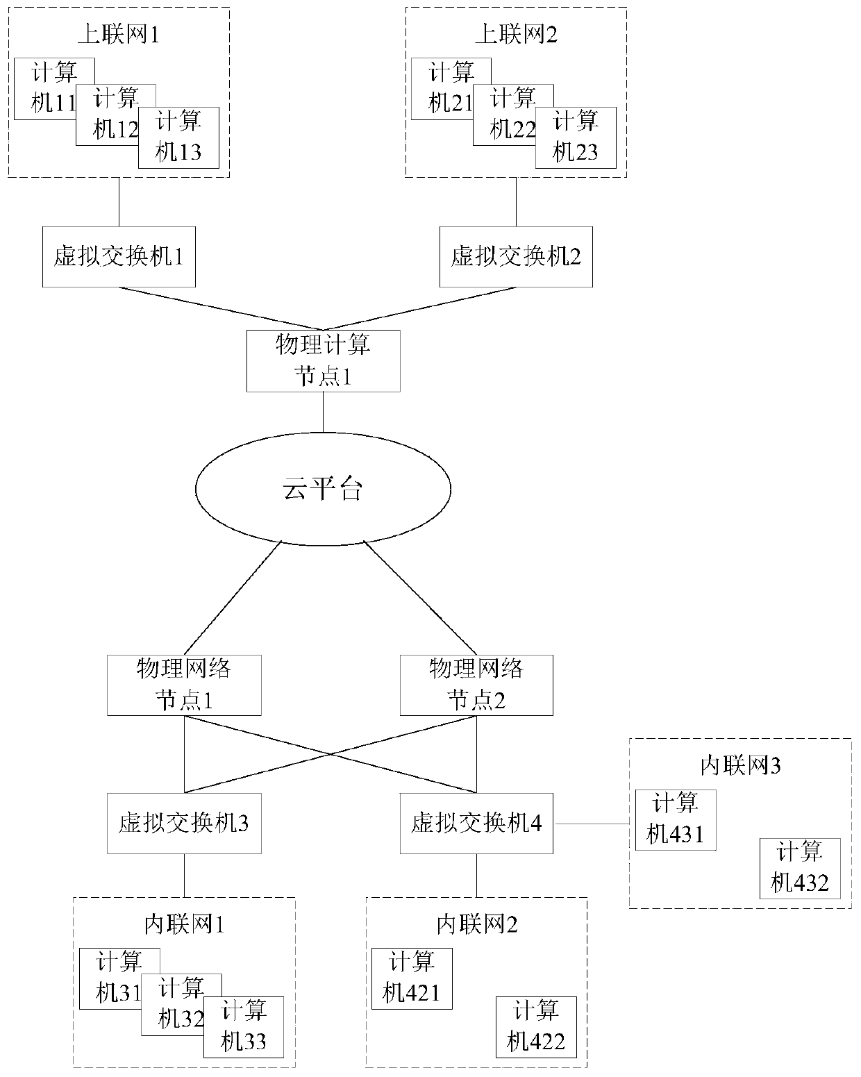
[0032] Taking a cloud platform distributed network architecture as an example, such as figure 1 As shown, the cloud platform is a distributed network system, including a physical network node 1, a physical network node 2, and a physical computing node 1, which are distributed in different places in the network system and are respectively responsible for the network function and computing function of the cloud platform. The network cable is connected to the network architecture of the...


PUM


Abstract

The invention relates to a distributed virtual switch and a configuration method, and the virtual switch is created by virtual switch software running on a physical machine to realize the function ofa network switch. The physical machine comprises a switch operation rule and virtual switch software. The configuration method comprises the following steps that 1, the cloud platform configures physical nodes; 2, virtual switch software and switch rules are configured; step 3, a virtual switch is built, and basic attributes are set; 4, one or more uplink networks of the virtual switch are set; 5,one or more physical nodes are added to the virtual switch; 6, the authority of the virtual switch and the binding node are set; and 7, the attribute of the cloud platform virtual switch is issued tothe physical node and enabled to take effect. The method can replace a physical switch to improve the utilization efficiency of network resources, has the advantages of rich functions, flexible configuration, convenience in operation and the like, and has very high engineering application value.

Description

technical field [0001] The invention relates to a network switch technology, in particular to a distributed virtual switch and a configuration method. Background technique [0002] A network switch is a key device that makes up a network system, providing more connection ports between networks to connect more computers. With the development of the Internet and information society, the number of computers connected to the network continues to increase, and the demand for network switch equipment continues to rise. There are two types of switches: WAN switches and LAN switches. WAN switches are mainly used in the field of telecommunications to provide a basic communication platform. The LAN switch is used in the local area network to connect terminal devices, such as PCs and network printers. [0003] The main functions of the switch include physical addressing, network topology, error checking, frame sequence, and flow control. At present, the switch also has some new fun...

Claims


Application Information

Patent Timeline
Patent Type & Authority Applications(China)
IPC IPC(8): H04L12/24H04L12/931H04L29/06H04L29/08
CPCH04L41/042H04L41/0823H04L49/354H04L49/70H04L63/0218H04L63/102H04L67/025H04L67/34
Inventor 金辉王文翔邸小丽
Owner 启迪云计算有限公司
Why Eureka
Try Eureka