Balanced vibration system

A vibration system and balance technology, applied in the direction of diaphragm fixation/tightening, sensors, electrical components, etc., can solve the problems of unilateral vibration distortion, large energy loss, low signal conversion efficiency, etc., to eliminate distortion and reduce power consumption. The effect of high power consumption and signal conversion efficiency

Pending Publication Date: 2019-07-12
潘国昌
View PDF0 Cites 11 Cited by
  • Summary
  • Abstract
  • Description
  • Claims
  • Application Information

AI Technical Summary

Problems solved by technology

[0004] In view of the deficiencies in the prior art above, the purpose of the present invention is to propose a balanced vibration

Method used


Image

  • Balanced vibration system
  • Balanced vibration system
  • Balanced vibration system

Examples


Embodiment 1

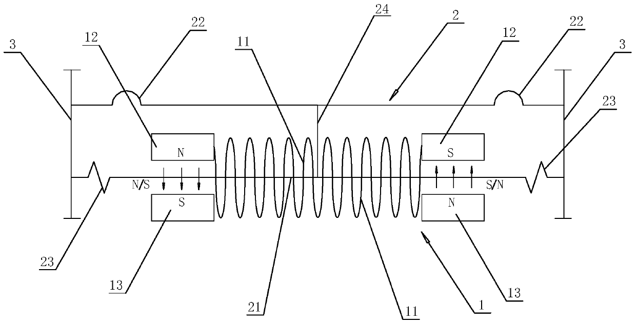
[0027] Embodiment 1, combining figure 1 , a balanced vibration system, including a magnetic circuit unit 1, a vibration unit 2 and a housing 3, the magnetic circuit unit 1 and the vibration unit 2 are located inside the housing 3, the magnetic circuit unit 1 is fixed on the housing 3, and the vibration The unit 2 is elastically connected with the casing 3, and the vibration unit 2 vibrates with the change of the magnetic field of the magnetic circuit unit 1 to realize vibration. The magnetic circuit unit 1 includes a set of magnetic circuit coils 11 and two magnet groups. The two magnet groups are respectively located at the left and right ends of the set of magnetic circuit coils 11 in the axial direction. Fixedly connected, the two terminals of the magnetic circuit coil 11 are fixed on the casing 3, and can be electrically connected to the signal source through wires. According to the law of electromagnetic conversion, the magnetic circuit coil 11 will generate an induced m...

Embodiment 2

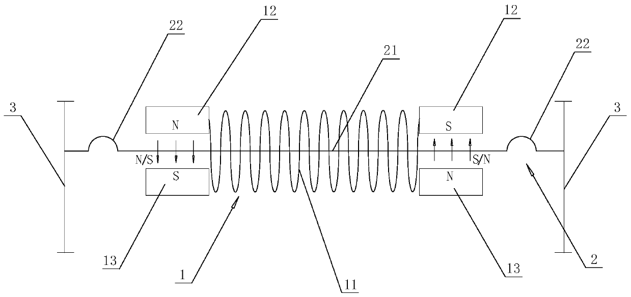
[0033] Example 2, combined with figure 2 , a balanced vibration system, including a magnetic circuit unit 1, a vibration unit 2 and a housing 3, the magnetic circuit unit 1 and the vibration unit 2 are located inside the housing 3, the magnetic circuit unit 1 is fixed on the housing 3, and the vibration The unit 2 is elastically connected with the casing 3, and the vibration unit 2 vibrates with the change of the magnetic field of the magnetic circuit unit 1 to realize vibration. The magnetic circuit unit 1 includes a magnetic circuit coil 11 and two magnet groups, and the two magnet groups are respectively located at the left and right ends of the magnetic circuit coil 11 axial direction, and the two ends of the magnetic circuit coil 11 are respectively fixed with the magnet groups located at the left and right ends of the magnetic circuit coil. The two terminals of the magnetic circuit coil 11 are fixed on the casing 3 and can be electrically connected to the signal source ...

Embodiment 3

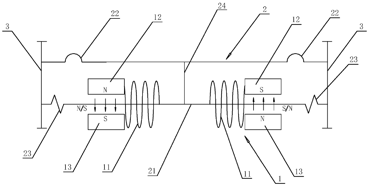
[0037] Embodiment 3, combining image 3 and Figure 4 , the principle of embodiment 3 is the same as that of embodiment 1, and the structure is basically the same. The difference between embodiment 3 and embodiment 1 is that the magnetic circuit unit 1 of embodiment 3 includes two sets of magnetic circuit coils 11, and two sets of magnetic circuit coils. The coils 11 are respectively located on opposite sides of the two magnet groups, that is, two sets of magnetic circuit coils 11 are located between the two magnet groups, and the opposite ends of the two sets of magnetic circuit coils 11 are fixedly connected to the corresponding magnet groups (such as image 3 shown). Simultaneously, two groups of magnetic circuit coils 11 can also be positioned at opposite sides of two magnet groups respectively, namely two groups of magnetic circuit coils 11 are positioned at the outside of two magnet groups, and the opposite end of two groups of magnetic circuit coils 11 is fixed with co...


PUM


Abstract

The invention discloses a balanced vibration system which comprises a magnetic circuit unit, a vibration unit and a shell, and the magnetic circuit unit and the vibration unit are located in the shell. Wherein the vibration unit comprises a balance iron core and a vibration diaphragm, the balance iron core is movably connected with the shell, the vibration diaphragm is fixed on the shell, and thebalance iron core can drive the vibration diaphragm to move. The magnetic circuit unit comprises a magnetic circuit coil and two magnet sets, the balance iron core is sleeved in the magnetic circuit coil, and the two magnet sets are located at the two ends of the axis direction of the balance iron core respectively. Each magnet set comprises two magnets, and the two magnets of the same magnet setare oppositely arranged on the two sides of the balance iron core. And when the magnetic coil is in a power-on state, the directions of the two magnet groups applied to the balance iron core are the same. Overall vibration of the iron core is balanced through the magnetic circuit unit and the vibration unit, so that the signal conversion efficiency is higher, power consumption is reduced, and distortion caused by unilateral vibration is eliminated.

Description

technical field [0001] The invention relates to the technical field of vibration, in particular to a balanced vibration system. Background technique [0002] The vibration system disclosed in the existing technology can be divided into two types in principle, one is the moving coil, and the other is the moving iron. The moving coil uses the vibration of the magnetic circuit coil to drive the vibration diaphragm to vibrate, and the moving iron is the magnetic line. The coil does not move, and one end of the balance iron core in the center of the coil vibrates to drive the vibrating diaphragm to vibrate. [0003] Because the moving iron of the prior art is in the center of the magnetic circuit coil, the magnetic change occurs at one end of the balance iron core due to the change of the coil current, so that one end of the balance iron core vibrates in the magnetic field, because one end of the balance iron core is vibrating, and the other end is fixed, so that An elastic cant...

Claims


Application Information

Patent Timeline
IPC IPC(8): H04R9/06H04R9/02
CPCH04R9/06H04R9/025H04R2400/11H04R11/02H04R7/18
Inventor 潘国昌刘宝军
Owner 潘国昌
Why Eureka
Try Eureka