
Coiled tubing tractor and working method thereof

A tractor and tubing technology, which is applied to coiled tubing tractors and their working fields, can solve the problems of tractor distortion and insufficient power, and achieve the effect of large traction force and increased traction force

Pending Publication Date: 2019-07-16
YANGTZE UNIVERSITY
View PDF0 Cites 1 Cited by
  • Summary
  • Abstract
  • Description
  • Claims
  • Application Information

AI Technical Summary

Problems solved by technology

When the tractor is working, the drilling mud is used as the power to drive the screw drive shaft to rotate, and the power is easy to obtain. However, the tractor of this patent has insufficient power when used, and the tractor is easily distorted during use.

Method used


Image

  • Coiled tubing tractor and working method thereof
  • Coiled tubing tractor and working method thereof
  • Coiled tubing tractor and working method thereof

Examples


Embodiment 1

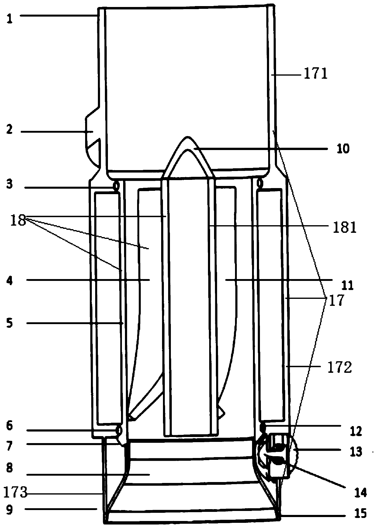
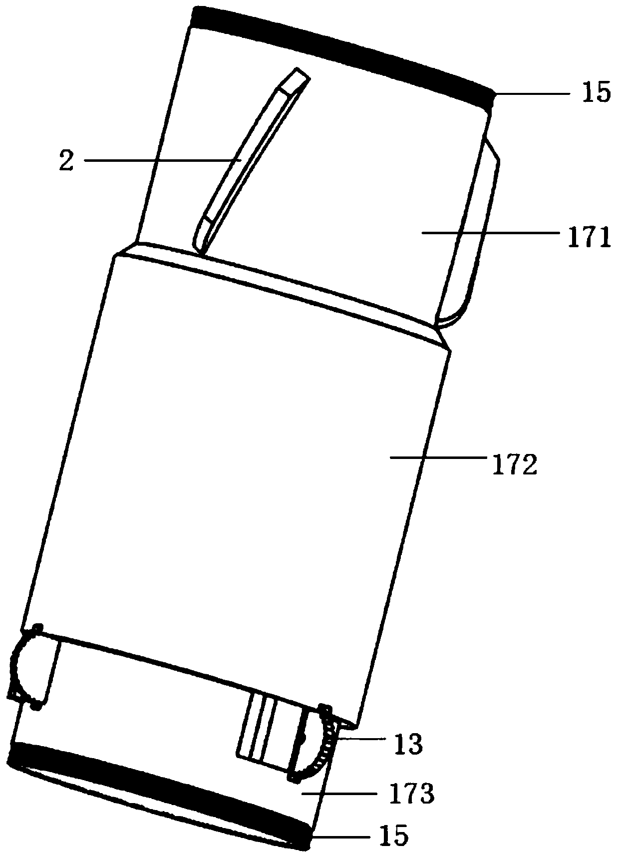
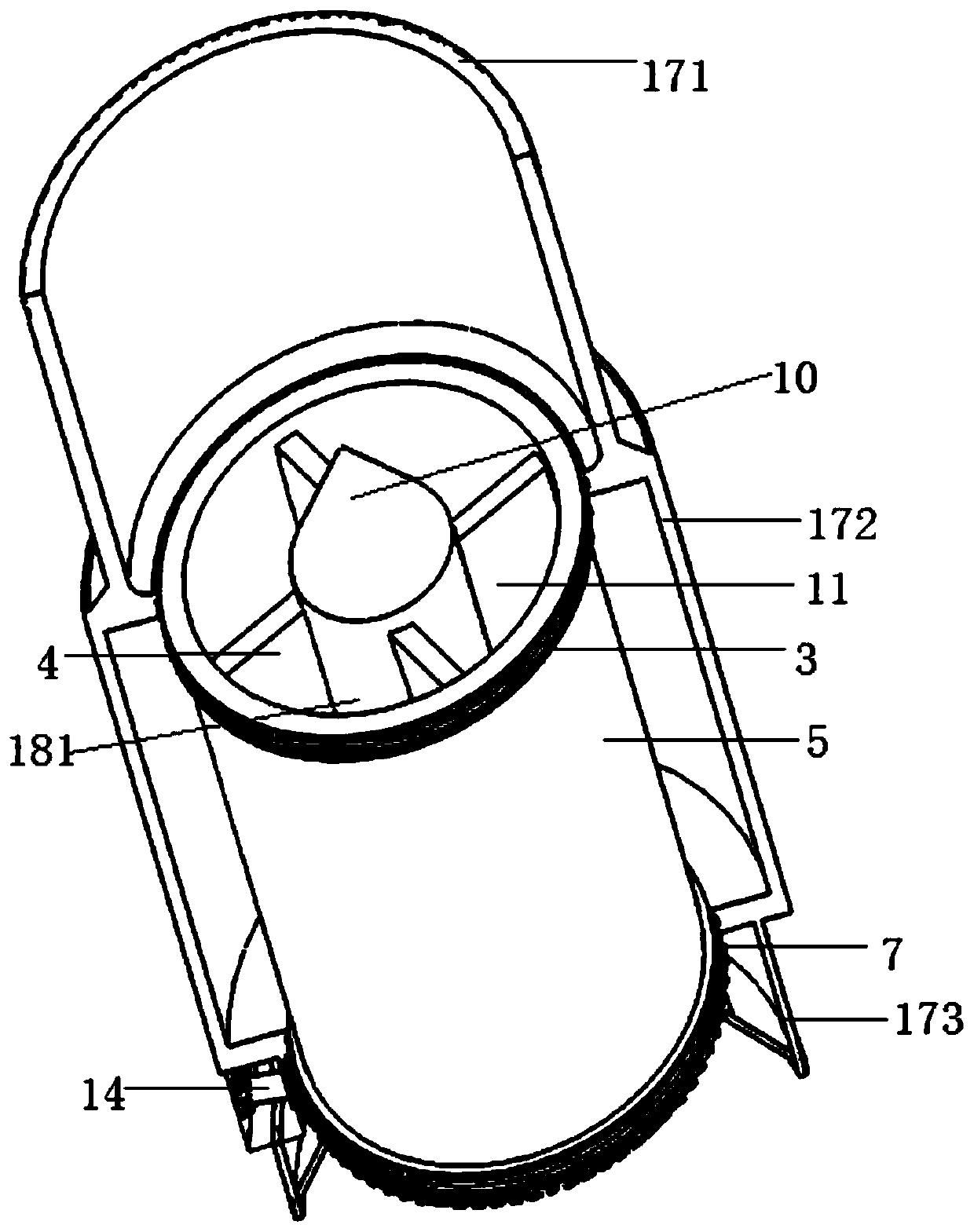
[0085] like Figure 1-Figure 6 As shown, a coiled tubing tractor is connected between the downhole power drilling tool and the coiled tubing, and includes a casing 17, a rotor 18 and a steering system, the casing 17 acts as a stator, and the rotor 18 and the steering system are arranged in the casing 17, The rotor 18 can rotate at high speed under the impact of the high-pressure drilling fluid to generate power; the steering system includes the main steering shaft 14, the auxiliary steering shaft 16 and the creeping wheel 13. The steering system is used to change the output direction of the power so that it drives the coiled tubing Advance in horizontal wells. The power generated by the drilling fluid is transmitted to the auxiliary steering shaft 16 and the crawling wheel 13 through the main steering shaft 14 to generate traction.

[0086] The rotor 18 includes a shaft 181 , and a plurality of blades are provided on the outer side of the shaft 181 . The blades at least incl...

Embodiment 2

[0098] A working method of a coiled tubing tractor, comprising the following steps:

[0099] (1) First install the coiled tubing tractor between the downhole motor and the coiled tubing;

[0100] (2) Turn on the surface mud pump, and the drilling fluid flows into the inside of the coiled tubing and enters the rotor inside the casing;

[0101] (3) Drilling fluid continuously impacts the rotor to make it rotate continuously, thereby driving the main steering shaft 14 to rotate;

[0102] (4) The main steering shaft 14 drives the auxiliary steering shaft 16 to rotate through the steering rack 7, and provides steering force for the climbing wheel 13, thereby enabling it to climb.

[0103] like Figure 1-Figure 4 As shown, the rotor 18 includes a shaft 181, and a plurality of blades are arranged on the outer side of the shaft 181 . The blades at least include blade II4 and blade II11. A guide cone 10 is provided on the upper part of the shaft 181, and the upper end of the guide c...

Embodiment 3

[0114] A coiled tubing tractor, the difference from Embodiment 1 is that the casing 17 is a hollow cylindrical structure.


PUM


Abstract

The invention provides a coiled tubing tractor and a working method thereof. The coiled tubing tractor is connected between an underground power drilling tool and a coiled tubing, and is characterizedby comprising a shell, a rotor and a steering system, the rotor and the steering system are arranged in the shell, and the rotor can rotate at a high speed under the impact action of high-pressure drilling fluid to generate power; and the steering system comprises a main steering shaft 14, an auxiliary steering shaft 16 and a crawling wheel 13 and is used for changing the output direction of power so as to drive the coiled tubing to advance in a horizontal well. Cable power supply is not needed, the possibility of underground accidents is reduced, and hydraulic driving is adopted, so that energy can be effectively saved; when the coiled tubing works, the tubing does not rotate, so that the wheel type tractor with larger traction force is adopted in the coiled tubing work; and when the coiled tubing is used for horizontal well drilling operation, the coiled tubing tractor can also play a role of a centralizer, and the coiled tubing can be effectively centered, so that abrasion is reduced.

Description

technical field [0001] The invention belongs to a traction device for horizontal well drilling, in particular, the invention relates to a coiled tubing tractor and a working method thereof. Background technique [0002] In recent years, with the continuous increase of the world's demand for oil, in order to enhance the recovery rate, most of the oil and gas exploitation adopts horizontal well drilling technology. In the process of oil and gas extraction, there are many factors that affect the cost of drilling. In China, coiled tubing underbalanced drilling technology has been gradually paid attention to because of its good maneuverability, no damage to the reservoir, fast tripping and short drilling cycle. Because the coiled tubing is always close to the lower surface of the wellbore when drilling a horizontal well, the resistance to the coiled tubing is too large, so the length of the horizontal well drilled is limited. The tractor can be used to reduce the resistance wel...

Claims


Application Information

Patent Timeline
IPC IPC(8): E21B23/08
CPCE21B23/08
Inventor 朱忠喜张迎进白宗玺
Owner YANGTZE UNIVERSITY
Learn More