
Engine lubricating system

A lubrication system and engine technology, which is applied in the direction of engine lubrication, engine components, engine cooling, etc., can solve the problems of reducing fuel consumption, high performance targets, and unreliable pistons, achieving energy saving and emission reduction effects, and high control flexibility , the effect of low difficulty in implementation

Inactive Publication Date: 2019-07-16
CHONGQING CHANGAN AUTOMOBILE CO LTD
View PDF6 Cites 2 Cited by
  • Summary
  • Abstract
  • Description
  • Claims
  • Application Information

AI Technical Summary

Problems solved by technology

[0002] At the current stage, the development of the engine lubrication system only selects technical solutions and designs performance parameters from the perspective of meeting reliability requirements, and there are situations where performance goals are much higher than actual needs, resulting in unnecessary waste of energy
The traditional piston cooling nozzle is directly installed on the main oil passage, opened and closed by a mechanical valve. When the oil pressure exceeds the design value, the nozzle starts to spray oil. The piston has no reliability risk, but it cannot always work in the optimal temperature range, which is not conducive to reducing Fuel consumption and reduced emissions, especially at low oil temperatures

Method used


Image

  • Engine lubricating system
  • Engine lubricating system
  • Engine lubricating system

Examples


Embodiment Construction

[0024] The present invention will be further described below in conjunction with the accompanying drawings.

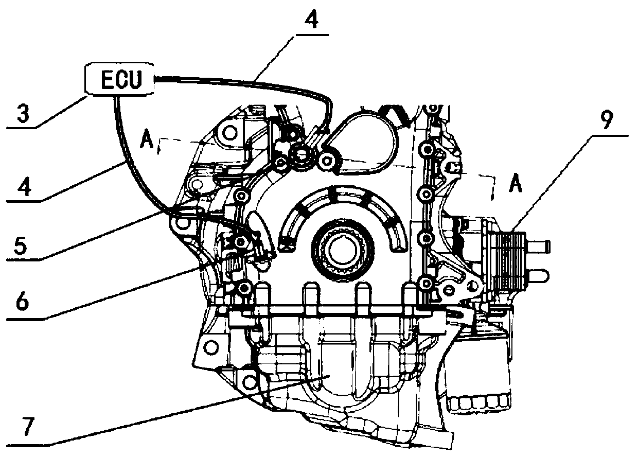
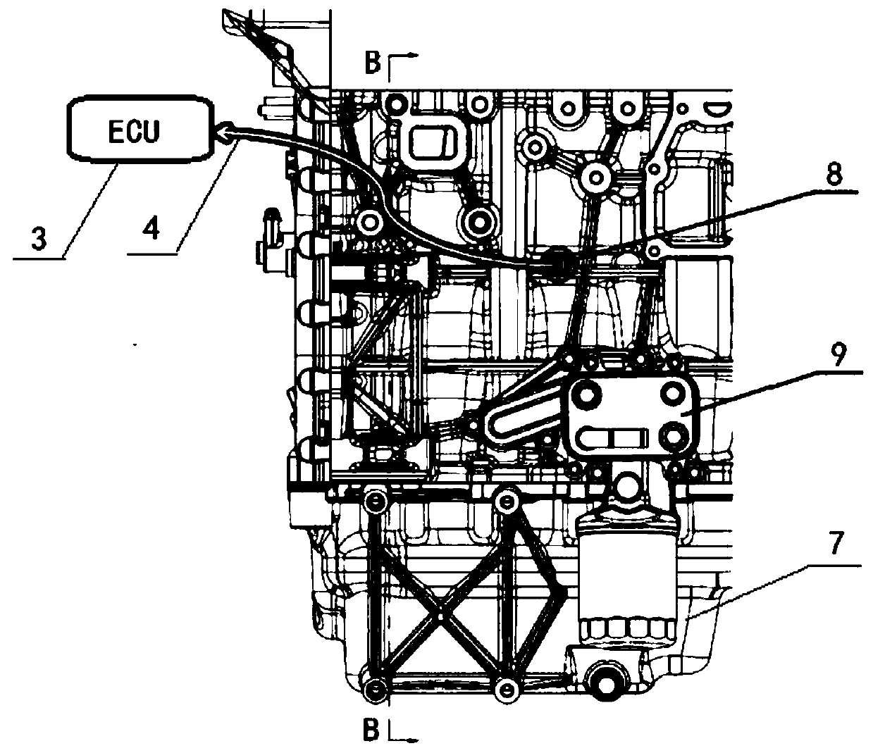
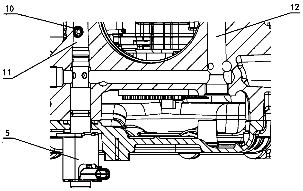
[0025] see Figure 1 to Figure 6 The engine lubricating system shown includes: a piston cooling nozzle oil passage 11 arranged on the engine block, a cylinder main oil passage 12 and a cylinder feedback oil passage 15, a control unit 3 arranged outside the engine, installed on The engine oil pan 7 below the engine block, the fully variable oil pump 14 located between the engine block below and the oil pan 7, the fully variable oil pump is the energy source of the entire lubricating system, and provides a sufficient amount of lubricating oil for the lubricating system. Its characteristics are:

[0026] An oil pressure oil temperature sensor 8 is installed on the main oil passage 12 of the cylinder body to sense the pressure and temperature of the engine oil, and convert it into an electrical signal and transmit it to the control unit 3;

[0027] A piston cooling contr...


PUM


Abstract

The invention relates to an engine lubricating system. The engine lubricating system comprises a piston cooling nozzle oil channel, a cylinder body main oil channel and a cylinder body feedback oil channel which are arranged in an engine cylinder body, a control unit arranged on the exterior of an engine, an engine oil disc installed on the lower surface of the engine cylinder body and a fully variable oil pump arranged between the lower surface of the engine cylinder body and the engine oil disc; an oil pressure and oil temperature sensor is installed on the cylinder body main oil channel andused for sensing the pressure and the temperature of engine oil, converting the pressure and the temperature into electrical signals and transmitting the electrical signals into the control unit; a piston cooling control valve is installed on the engine cylinder body and located between the piston cooling nozzle oil channel and the cylinder body main oil channel; and a piston cooling nozzle is arranged on the piston cooling nozzle oil channel and controlled by the piston cooling control valve. According to the engine lubricating system, the performance objectives of the system can be set at the low level, a piston can always work within the appropriate temperature range, therefore, power consumption of the oil pump is reduced, oil consumption of the whole engine is reduced, and emission is improved.

Description

technical field [0001] The invention relates to an automobile engine, in particular to an engine lubricating system. Background technique [0002] At the current stage, the development of the engine lubrication system only selects technical solutions and designs performance parameters from the perspective of meeting reliability requirements, and there are situations where performance goals are much higher than actual needs, resulting in unnecessary waste of energy. The traditional piston cooling nozzle is directly installed on the main oil passage, opened and closed by a mechanical valve. When the oil pressure exceeds the design value, the nozzle starts to spray oil. The piston has no reliability risk, but it cannot always work in the optimal temperature range, which is not conducive to reducing Fuel consumption and reduced emissions, especially at low oil temperatures. [0003] CN 204729147U discloses "an engine lubricating system", which is characterized in that: the lubr...

Claims


Application Information

Patent Timeline
IPC IPC(8): F01M1/02F01M1/20F01P3/08F01P7/14F01M1/10
CPCF01M1/02F01M1/10F01M1/20F01M2001/0253F01M2001/1028F01P3/08F01P7/14F01P2007/146
Inventor 彭海尹强李仙
Owner CHONGQING CHANGAN AUTOMOBILE CO LTD
Learn More