Service bridge sling fatigue life probability assessment method
A fatigue life and sling technology, applied in the field of safety assessment of bridges in service, can solve problems such as the difficulty of accurately detecting materials, and achieve the effect of reasonable prediction methods and strong generalization
Pending Publication Date: 2019-07-16
CHANGSHA UNIVERSITY OF SCIENCE AND TECHNOLOGY
View PDF3 Cites 16 Cited by
- Summary
- Abstract
- Description
- Claims
- Application Information
AI Technical Summary
Problems solved by technology
Furthermore, another necessary condition for the crack growth analysis method is to obtain the initial crack of the material. Due to the limitation of objective factors such as material quality and surface roughness, it is still difficult to accurately detect the initial crack of the material.
Method used
View moreImage
Smart ImageViewing Examples

Examples
Embodiment 1
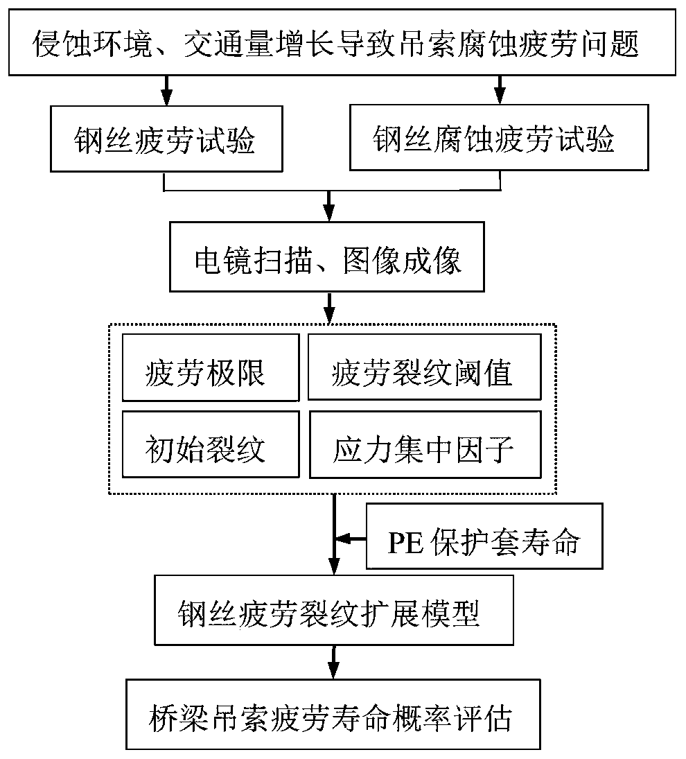
[0066] Such as Figure 1-4 : a method for assessing the probability of fatigue life of a bridge sling in service provided by the present embodiment, comprising the following steps:
Login to View More PUM
 Abstract
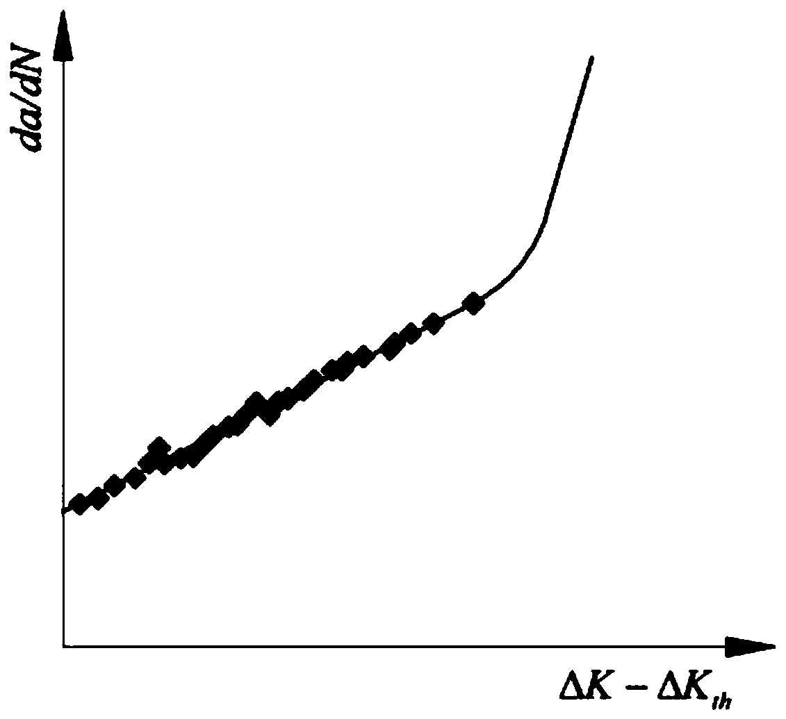
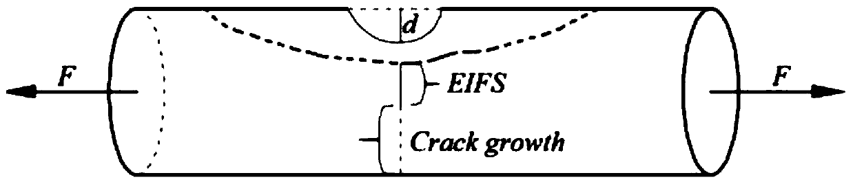
According to the service bridge sling fatigue life probability assessment method disclosed by the invention, fatigue test data are fitted by implementing fatigue crack propagation tests of a bridge sling high-strength steel wire under different stress ratios, and a relational expression of fatigue crack growth analysis model parameters and stress ratios is obtained; a stress concentration effect caused by a corrosion pit is fused into the stress strength factor model, and a sling high-strength steel wire fatigue crack propagation analysis model is established by adopting small crack growth andnear-threshold crack growth analysis; an initial crack is obtained on the basis of an equivalent initial crack principle, the fatigue life of a single steel wire is obtained by integrating a steel wire crack propagation model, a correlation coefficient is introduced, the influence of stress redistribution of a sling after wire breakage is considered, and life evaluation of the bridge sling underthe corresponding wire breakage rate condition can be achieved. The prediction method is reasonable and high in generalization performance, and can be used for predicting the fatigue life of the long-span bridge sling.
Description
technical field [0001] The invention relates to the field of safety assessment of bridges in service, in particular to a method for predicting the fatigue life of suspension cables of long-span bridges. Background technique [0002] The slings of the built under-supported arch bridges and suspension bridges are composed of several high-strength steel wires, which are the key load-bearing components connecting the bridge deck system and the upper main structure. With the increasing traffic volume, the fatigue problem of bridge hangers is gradually appearing. In addition, the sling is in a state of high stress for a long time, and if it is not properly protected, it is prone to steel wire corrosion. Corrosion leads to a reduction in the cross-sectional area of the steel wire, and local rust pits can also lead to stress concentration, which further aggravates the fatigue degradation process of the bridge sling, resulting in a greatly reduced service life. Under the combined...
Claims
Login to View More Application Information
Patent Timeline
 IPC IPC(8): G06F17/50
CPCG06F30/13G06F2119/04Y02P90/30
Inventor 马亚飞张建仁欧阳清波王磊郭忠照
Owner CHANGSHA UNIVERSITY OF SCIENCE AND TECHNOLOGY
Features
- R&D
- Intellectual Property
- Life Sciences
- Materials
- Tech Scout
- Unparalleled Data Quality
- Higher Quality Content
- 60% Fewer Hallucinations
Learn More Browse by: Latest US Patents, China's latest patents, Technical Efficacy Thesaurus, Application Domain, Technology Topic, Popular Technical Reports.
© 2025 PatSnap. All rights reserved.Legal|Privacy policy|Modern Slavery Act Transparency Statement|Sitemap|About US| Contact US: help@patsnap.com