Three-dimensional damping hinge base for parallel machine tool vibration reducing

A hinge seat and machine tool technology, which is applied in the field of damping and vibration reduction, can solve the problems of large motion range, inability to achieve multi-dimensional vibration reduction, and inability to meet the rigidity requirements of parallel machine tools, etc., and achieve the effect of high motion rigidity

Active Publication Date: 2019-07-19
NANJING UNIV OF SCI & TECH
View PDF9 Cites 1 Cited by
  • Summary
  • Abstract
  • Description
  • Claims
  • Application Information

AI Technical Summary

Problems solved by technology

[0004] Chinese patent CN101956780A discloses a viscous damper. This mechanism vulcanizes the elastic body at both ends of the cylinder body, the cylinder body and the piston rod into one, which improves the initial stiffness of the mechanism, but still cannot meet the stiffness requirements of parallel machine tools, and cannot Realize multi-dimensional vibration reduction; Chinese patent CN104154170A discloses a multi-dimensional vibration reduction platform in parallel configuration, which is a vibration reduction device composed of multiple piston dampers in parallel, which can achieve multi-dimensional vibration reduction, and the stiffness and damping can be adjusted. For vibration isolation of important instruments and equipment
However, its large range of motion cannot meet the rigidity requirements of parallel machine tools and the requirements for suppressing high-frequency micro-vibration

Method used


Image

  • Three-dimensional damping hinge base for parallel machine tool vibration reducing
  • Three-dimensional damping hinge base for parallel machine tool vibration reducing
  • Three-dimensional damping hinge base for parallel machine tool vibration reducing

Examples


Embodiment approach

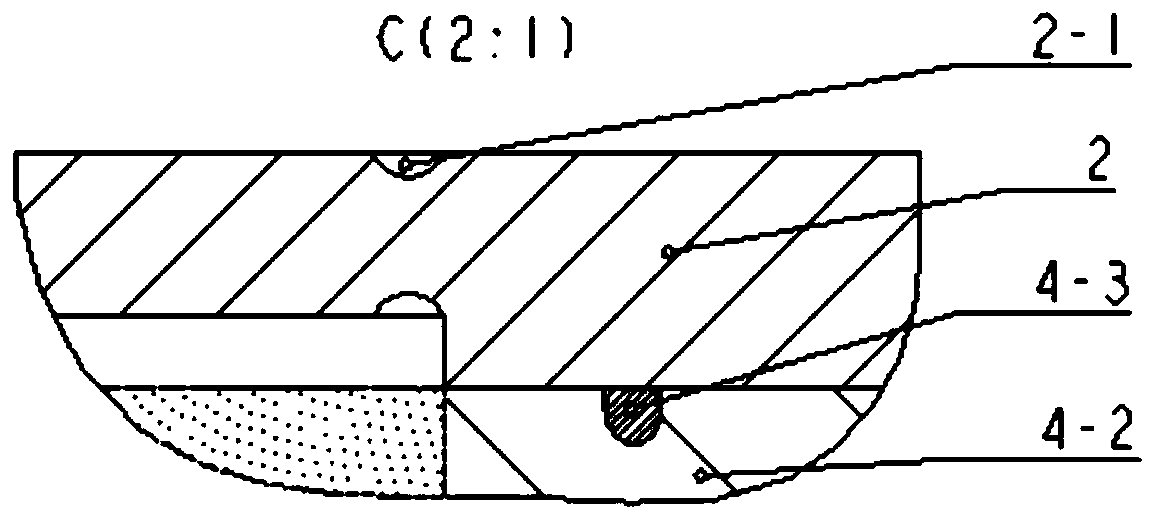
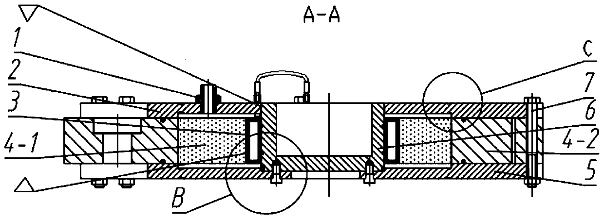
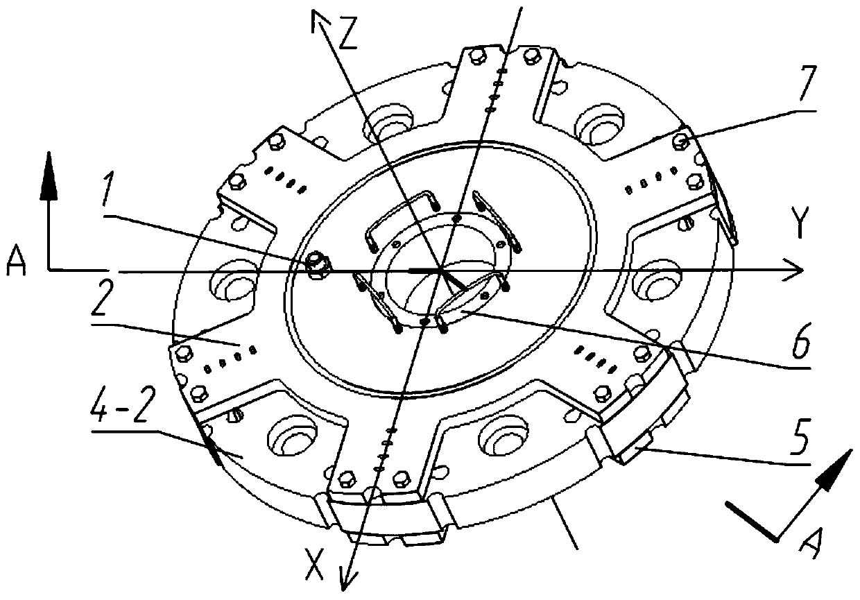
[0030] As an embodiment, the upper cylinder head 2 , the lower cylinder head 5 , and the support plate 4 - 2 are connected by bolts 7 , and the bolts connect the position of the teeth structure of the upper cylinder head 2 and the lower cylinder head 5 .

[0031] Preferably, the support plate 4-2 is provided with multiple sets of connecting holes, each set of connecting holes includes two through holes 4-5, and each through hole is provided with a bolt 7; this structure is equivalent to Figure 10 In the mechanism shown, the upper and lower cylinder heads fixedly connected with the hinge sleeve 6 form a parallelogram constraint, so that the hinge sleeve 6 can not only ensure translation but also slightly move in the direction of the Z axis.

[0032] As an implementation, the upper cylinder head 2 is provided with an oil delivery port joint 1 for filling the oil storage cavity.

[0033] In some embodiments, the upper cylinder cover 2 and the hinge sleeve 6 are fixedly connected...


PUM


Abstract

The invention discloses a three-dimensional damping hinge base for parallel machine tool vibration reducing. An upper cylinder cover, damping liquid bags, a rigidity porous plate, a supporting plate,a lower cylinder cover and a hinge sleeve are included. The upper cylinder cover and the lower cylinder cover are fixedly connected with the upper end and the lower end of the hinge sleeve correspondingly. The damping liquid bags, the rigidity porous plate and the supporting plate are sequentially arranged in a cavity between the upper cylinder cover and the lower cylinder cover from interior to exterior. The supporting plate is fixedly connected with the upper cylinder cover and the lower cylinder cover. The inner side and the outer side of the rigidity porous plate are fixedly connected withthe damping liquid bags and the supporting plate. The damping liquid bags are attached to the hinge sleeve. The multiple damping liquid bags are arranged on one circle of the hinge sleeve, and the adjacent damping liquid bags are connected through capillary oil conveying pipes. An oil storage cavity is formed between the rigidity porous plate and the upper cylinder cover. Liquid in the upper oilstorage cavity and liquid in a lower oil storage cavity are in communication through the rigidity porous plate. A second seal ring is arranged between the hinge sleeve and each damping liquid bag. Theupper cylinder cover and the lower cylinder cover are symmetrically arranged relative to the hinge sleeve. The upper cylinder cover and the lower cylinder cover are of a tooth-shaped structure. The tooth number is 2n, and n is larger than or equal to 2. The supporting plate is provided with a plurality of seams corresponding to tooth positions. The three-dimensional damping hinge base can achievemulti-dimension vibration reducing.

Description

technical field [0001] The invention relates to the field of damping and vibration reduction, in particular to a three-dimensional damping hinge seat used for vibration reduction of a parallel machine tool. Background technique [0002] Viscous dampers are widely used in machinery, vehicles, aerospace and military engineering as an excellent energy-dissipating and vibration-absorbing structural component. The common viscous damper is a hydraulic cylinder type, which is mainly composed of a piston head, a piston rod, a cylinder body and a seal. The damping chamber inside the oil cylinder is divided into two damping chambers. The damping chamber is filled with viscous liquid with high viscosity. When the piston moves relative to the oil cylinder, the liquid sealed in the damping chamber on the pressure side is squeezed, and the pressure It rises and flows from the gap or small hole between the piston head and the cylinder to another damping chamber. The pressure difference be...

Claims


Application Information

Patent Timeline
Patent Type & Authority Applications(China)
IPC IPC(8): B23Q11/00
CPCB23Q11/0032
Inventor 李开明董立磊舒阳葛帅帅周旖鋆
Owner NANJING UNIV OF SCI & TECH
Why Eureka
Try Eureka