Outer wall polishing device for stainless steel tubes

A stainless steel tube and polishing device technology, applied in grinding/polishing equipment, machine tools designed for grinding workpiece rotating surfaces, grinding workpiece supports, etc., can solve high maintenance costs, high energy consumption of motors, long time consumption, etc. problem, to achieve the effect of low maintenance cost, simple motor shaft load, and short time consumption

Active Publication Date: 2019-07-19
佛山市南海品三能金属制品有限公司
View PDF8 Cites 11 Cited by
  • Summary
  • Abstract
  • Description
  • Claims
  • Application Information

AI Technical Summary

Problems solved by technology

[0003] The above-mentioned existing stainless steel pipe outer wall polishing device can also clean and dry the polished stainless steel pipe outer surface through the spray pipe device installed on the lifting cover and the brush installed on the filter plate after polishing, but in practice In the process of use, because the movable rod needs to drive the polishing pad to move on the surface of the rotating stainless steel tube to achieve polishing, the time for the polishing pad to move in translation to polish a complete stainless steel tube is related to the length of the stainless steel tube to be polished. The pipe takes a long time and the polishing efficiency is low, and the above-mentioned existing stainless steel pipe outer wall polishing device drives the steel pipe splint to rotate and the movable rod to move in translation at the same time through a motor, and the rotation of the stainless steel pipe to be polished and the translation of the polishing pad during polishing There will be resistance interference between them, which will easily cause the motor shaft to be overloaded and break. The energy consumption of the motor is large when it is running. The motor needs to be replaced frequently, and the use and maintenance cost is high.

Method used


Image

  • Outer wall polishing device for stainless steel tubes
  • Outer wall polishing device for stainless steel tubes
  • Outer wall polishing device for stainless steel tubes

Examples


Embodiment Construction

[0018] In the following, the present invention will be further described in conjunction with the accompanying drawings and specific embodiments, so as to understand more clearly the technical idea claimed in the present invention.

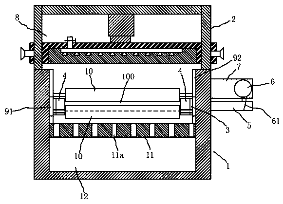
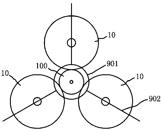
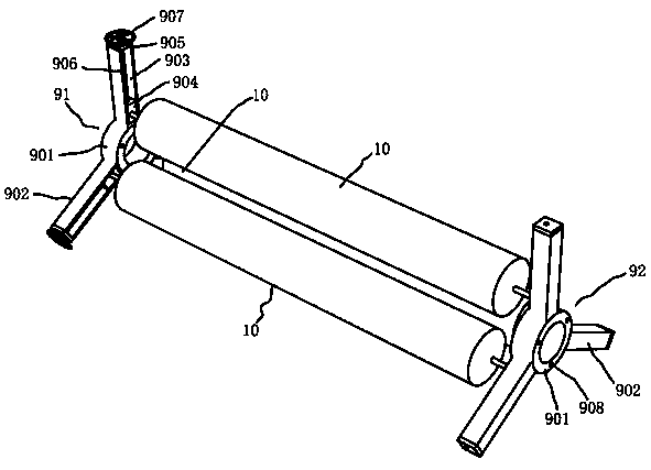
[0019] like Figure 1-5 The outer wall polishing device of a stainless steel pipe shown in the present invention includes a casing 1, a bracket 2, a rotating base 3, a steel pipe splint 4, a transmission shaft 5, a motor 6, a motor seat plate 7, a lifting cover 8, and a first polishing roller seat 91 , the second polishing roller seat 92 and the polishing roller 10, the bracket 2 is arranged on the upper end of the casing 1, the rotating base 3 is symmetrically installed on the left and right side walls of the casing 1, and the steel pipe splint 4 is fixedly installed on the rotating base 3, one of which The rotating base 3 on the side is fixedly connected with the transmission shaft 5, the transmission shaft 5 is connected with the motor shaft of ...


PUM


Abstract

The invention discloses an outer wall polishing device for stainless steel tubes. To-be-processed stainless steel tubes are clamped and fixed by steel tube clamping plates during polishing and processing, and are driven by motors to rotate; the to-be-processed stainless steel tubes are positioned on the centers of three polishing rollers which are distributed in the shape of a triangle; when the to-be-processed stainless steel tubes rotate, quick friction between the to-be-processed stainless steel tubes and the roller surfaces of the polishing rollers is generated, so that the polishing rollers and the to-be-processed stainless steel tubes relatively roll to realize polishing the stainless steel tubes; the stainless steel tubes rotate by several circles, so that the complete surfaces of the stainless steel tubes are polished, and therefore, polishing efficiency of the outer wall polishing device is higher than that of an existing mode of horizontally moving a polishing pad on the surfaces of rotating stainless steel tubes to accomplish polishing, and time for polishing the stainless steel tubes of certain length is shorter; and moreover, during processing and polishing, the motorsonly need to output power for rotation action of the stainless steel tubes, and motor shaft load of the motors is simpler, so that energy consumption during motor operation is lower; and the motors do not need to frequently replace, so that use and maintenance cost is lower.

Description

technical field [0001] The invention belongs to the technical field of production and processing of stainless steel pipes, and in particular relates to an outer wall polishing device for stainless steel pipes. Background technique [0002] At present, the existing stainless steel tube outer wall polishing device, as disclosed in the Chinese invention patent (publication number CN109465688), includes a shell, a bracket, a lifting cover, a filter plate, a rotating base, a steel pipe splint, a transmission shaft, a motor, a movable rod, and a polishing pad , turntable, connecting rod and gasket, the bracket is set on the upper end of the shell, the lifting cover is installed on the bracket, the filter plate is installed in the shell, and the rotating base is symmetrically installed on the left and right side walls of the shell above the filter plate , the steel pipe splint is fixed on the rotating base, and the rotating base on one side is fixedly connected with the drive shaft...

Claims


Application Information

Patent Timeline
Patent Type & Authority Applications(China)
IPC IPC(8): B24B5/04B24B27/00B24B41/06
CPCB24B5/04B24B27/0076B24B41/067
Inventor 曾少亮
Owner 佛山市南海品三能金属制品有限公司
Why Eureka
Try Eureka