Al technical title is built by PatSnap Al team. It summarizes the technical point description of the patent document.
A high-precision, printing press technology, used in printing presses, rotary printing presses, general-purpose parts of printing machinery, etc., can solve the problems of low overprinting accuracy, and the center point cannot be highly overlapped, and achieve the effect of high overprinting accuracy.
Active Publication Date: 2019-07-19
KUNSHAN RUIYONGCHENG PRECISION EQUIP
View PDF15 Cites 2 Cited by
Summary
Abstract
Description
Claims
Application Information
AI Technical Summary
This helps you quickly interpret patents by identifying the three key elements:
Problems solved by technology
Method used
Benefits of technology
Problems solved by technology
[0002] At present, when using CCD positioning pad printing, that is, when repeatedly overprinting different patterns in a certain concave area based on the same center point, there is a problem that the center points of different patterns that are repeatedly positioned and overprinted cannot be highly overlapped, resulting in low overprinting accuracy
Method used
Image
Click on the blue label to locate the original text in one second.
Reading with bidirectional positioning of images and text.
Examples
Embodiment 1
[0080] refer to figure 1 , Embodiment 1 of the present invention provides a method for repeated overprinting of concave surfaces with high precision. The method is mainly aimed at blind holes on cover plates of electronic products. The method includes the following steps:
[0081] Wherein, the steps of printing the first pattern are:
[0082] Step S1, using the blind hole positioning mechanism to grab the bottom of the blind hole or the aperture halo, and automatically record its first center coordinates X00, Y00 and R00;
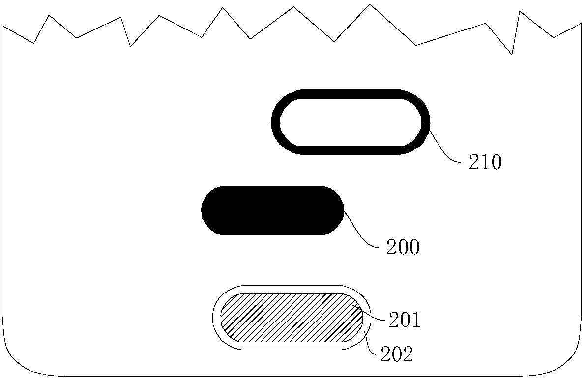
[0083] Step S2, collect the first pattern 210 matching the bottom 201 of the blind hole from the ink-taking mechanism, and print it on the cover plate of the electronic product;
[0084] Step S3, using the blind hole positioning mechanism to capture the data of the second center coordinates X1, Y1 and R1 of the first pattern 210 on the cover;
[0085] Step S4, obtain the difference between the second center coordinates X1, Y1, R1 of the first pattern 210 ...
Embodiment 2
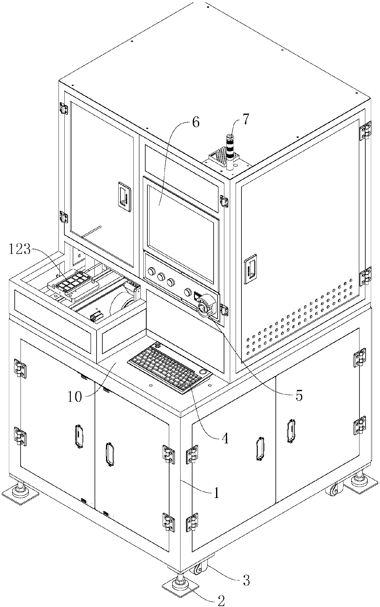
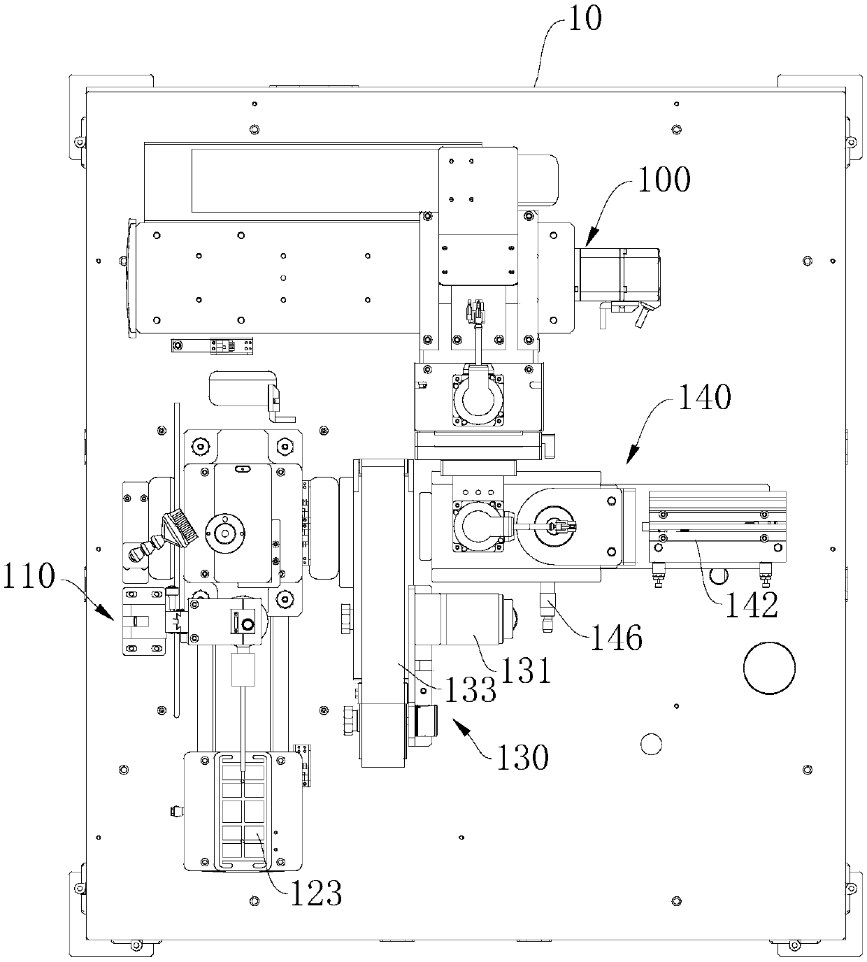
[0098] combine figure 2 , image 3 , Figure 4 and Figure 5 The embodiment of the present invention also provides a blind hole printing machine, which includes a frame 1, a support table 10, a Y-axis linear module, a workbench 123, a blind hole positioning mechanism 110, an ink taking mechanism 140, a moving Printing mechanism 100 and rubber head cleaning mechanism 130. Wherein, the frame 1 is a basic component of the blind hole printing machine, and it is used for installing the support table 10 . In addition, the blind hole printing machine also includes support feet 2, transfer pulleys 3, keyboard 4, emergency stop button 5, touch screen 6, three-color indicator light 7, and the support feet 2 and transfer pulleys 3 are arranged on the far side of the frame 1. One side of the support platform 10, the keyboard 4 is installed on the support platform 10, the emergency stop button 5 is used for the emergency stop operation of the blind hole printing machine, and the touch...
PUM
Abstract
The invention provides a concave surface high-precision repeated overprinting method and a blind hole printing machine, and relates to the technical field of blind hole printing. The concave-concave high-precision repeated overprinting method comprises the steps that a blind hole positioning mechanism is used for grabbing the bottom or a hole mouth light ring of a blind hole, and the first centralcoordinates X00, Y00 and R00 of the blind hole are automatically recorded; a first pattern matched with the bottom of the blind hole is collected from an ink taking mechanism, and the first pattern is printed on a cover plate of an electronic product; the blind hole positioning mechanism is used for grabbing data of the second central coordinates X1, Y1 and R1 of the first pattern on the cover plate; and a difference between the second central coordinates X1, Y1 and R1 of the first pattern and the first central coordinates X00, Y00 and R00 is obtained through automatic operation of a soft body, and then the first pattern is printed on the bottom of the blind hole after the difference is automatically compensated. The concave-concave high-precision repeated overprinting method is high in printing precision and capable of enabling the center points of different patterns to be highly overlapped.
Description
technical field [0001] The invention relates to the technical field of blind hole printing, in particular to a concave surface high-precision repeated overprinting method and a blind hole printing machine. Background technique [0002] At present, when using CCD positioning pad printing, that is, when repeatedly overprinting different patterns in a certain concave area based on the same center point, the center points of different patterns that are repeatedly positioned and overprinted cannot be highly overlapped, resulting in low overprinting accuracy. Contents of the invention [0003] The purpose of the present invention is to provide a concave high-precision repeated overprinting method, which has high overprinting accuracy and can make the central points of different patterns highly overlap. [0004] Another object of the present invention is to provide a blind hole printing machine, which has a high degree of automation and good printing effect. [0005] Embodiments...
Claims
Application Information
Patent Timeline
Application Date:The date an application was filed.
Publication Date:The date a patent or application was officially published.
First Publication Date:The earliest publication date of a patent with the same application number.
Issue Date:Publication date of the patent grant document.
PCT Entry Date:The Entry date of PCT National Phase.
Estimated Expiry Date:The statutory expiry date of a patent right according to the Patent Law, and it is the longest term of protection that the patent right can achieve without the termination of the patent right due to other reasons(Term extension factor has been taken into account ).
Invalid Date:Actual expiry date is based on effective date or publication date of legal transaction data of invalid patent.

