Check patentability & draft patents in minutes with Patsnap Eureka AI!

Pedal feel simulator for vehicle and vehicle having same

A simulator and pedal technology, applied in the field of vehicles, can solve the problems of slow response speed of the braking system, inconvenience for the driver, poor braking performance, etc., and achieve the effect of rapid signal transmission, fast braking response and reasonable braking force

Active Publication Date: 2021-09-03
BYD CO LTD
View PDF0 Cites 0 Cited by
  • Summary
  • Abstract
  • Description
  • Claims
  • Application Information

AI Technical Summary

Problems solved by technology

However, the response speed of the brake system using hydraulic transmission mechanism or pneumatic transmission mechanism is slow and the braking performance is poor, which brings great inconvenience to the actual operation of the driver.

Method used


Image

  • Pedal feel simulator for vehicle and vehicle having same
  • Pedal feel simulator for vehicle and vehicle having same
  • Pedal feel simulator for vehicle and vehicle having same

Examples


Embodiment 1

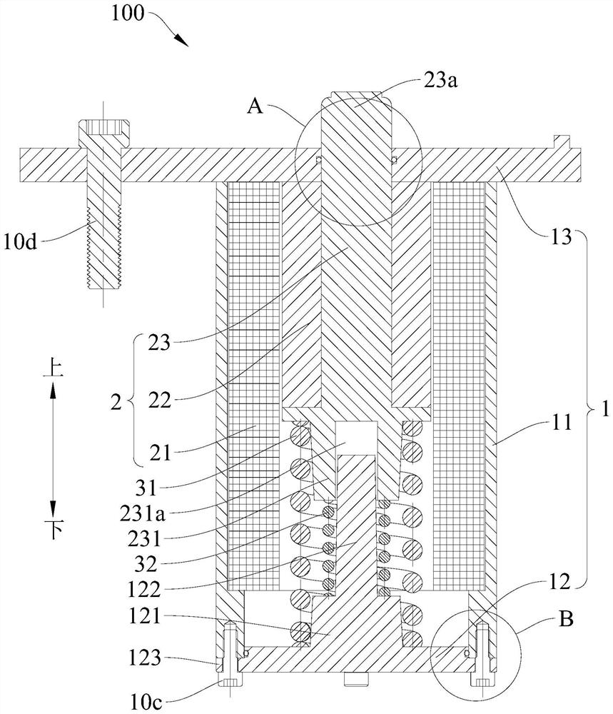
[0072] In this example, if Figure 1-Figure 7 As shown, the pedal feel simulator 100 includes a housing 1 , a linear motor 2 , a first elastic member 31 and a second elastic member 32 .

[0073] The housing 1 includes a main cylinder body 11, a bottom cover 12 and a fixed plate 13. The main cylinder body 11 is roughly formed into a cylindrical structure, the axial ends of the main cylinder body 11 are open, and the bottom cover 12 is arranged on the axial direction at one end (for example, if figure 1 middle lower end), the fixed plate 13 is located at the other axial end of the main cylinder body 11 (for example, as figure 1 The upper end of the middle), so that the bottom cover 12, the main cylinder body 11 and the fixed plate 13 jointly define a closed accommodation space. Specifically, as Figure 1-Figure 6 As shown, a first connecting portion 111 is formed on the upper end of the main cylinder body 11, and the first connecting portion 111 protrudes outward along the ra...

Embodiment 2

[0082] Such as Figure 8 As shown, the structure of this embodiment is substantially the same as that of Embodiment 1, wherein the same components use the same reference numerals, the difference is: when the driver does not step on the pedal 101 and the pedal feeling simulator 100 is in the initial position, the first Both the elastic member 31 and the second elastic member 32 are in a natural state, the two ends of the first elastic member 31 are respectively against the inner wall of the housing 1 and the second end 23b of the motor push rod 23, and the lower end of the second elastic member 32 is in contact with the second end 23b of the motor push rod 23. The inner wall of the housing 1 is in contact with each other, and the upper end of the second elastic member 32 is spaced apart from the second end 23 b of the motor push rod 23 . When the driver steps on the pedal 101, the first elastic member 31 first works to apply an elastic force to the motor push rod 23. When the d...


PUM


Abstract

The invention discloses a pedal feel simulator for a vehicle and a vehicle having the same. The vehicle includes a pedal, the pedal feel simulator includes a casing, a linear motor and two elastic parts, and the linear motor includes a motor primary, a motor secondary and a motor The push rod, the primary of the motor is fixed on the inner wall of the housing, the secondary of the motor is set in the primary of the motor, the secondary of the motor cooperates with the primary of the motor so that the secondary of the motor can move axially relative to the primary of the motor, and the secondary of the motor is sheathed on the push rod of the motor To drive the motor push rod to move synchronously, the first end of the motor push rod extends out of the shell to be suitable for being connected with the pedal; two elastic parts are respectively arranged in the shell, and the lengths of the two elastic parts are different, and the two ends of each elastic part respectively fit on the inner wall of the housing and the second end of the motor push rod. According to the pedal feeling simulator for vehicles of the present invention, the response speed is fast, the braking effect is good, and at the same time, the driver can be provided with good "braking feeling", especially pedal braking feeling.

Description

technical field [0001] The invention relates to the technical field of vehicles, in particular to a pedal feeling simulator for a vehicle and a vehicle with the same. Background technique [0002] In the related art, the pedals in the vehicle mainly use a hydraulic transmission mechanism or a pneumatic transmission mechanism for power transmission, so as to realize braking of the vehicle. However, the response speed of the brake system adopting the hydraulic transmission mechanism or the pneumatic transmission mechanism is relatively slow, and the braking performance is poor, which brings great inconvenience to the actual operation of the driver. Contents of the invention [0003] The present invention aims to solve at least one of the technical problems existing in the prior art. For this reason, the present invention proposes a kind of pedal feel simulator that is used for vehicle, and described pedal feel simulator has fast response speed, has good braking effect, can ...

Claims


Application Information

Patent Timeline
Patent Type & Authority Patents(China)
IPC IPC(8): B60T8/40B60T7/04
CPCB60T7/042B60T8/409
Inventor 滕俊辉王铁君李传博刘苏丽
Owner BYD CO LTD
Features
  • R&D
  • Intellectual Property
  • Life Sciences
  • Materials
  • Tech Scout
  • Unparalleled Data Quality
  • Higher Quality Content
  • 60% Fewer Hallucinations
Learn More