Bridge inhaul cable group cable force synchronous monitoring method and system based on microwave radar

A microwave radar and bridge technology, applied in radio wave measurement systems, force/torque/power measuring instruments, radio wave reflection/re-radiation, etc., can solve problems such as error-prone, micro-motion observation signal aliasing, and low efficiency , to achieve the effect of non-contact monitoring

Active Publication Date: 2019-07-19
SOUTHEAST UNIV
View PDF5 Cites 18 Cited by
  • Summary
  • Abstract
  • Description
  • Claims
  • Application Information

AI Technical Summary

Problems solved by technology

If microwave radar equipment is used to monitor the frequency of the cable group, when the distance between the microwave radar equipment and the monitoring cable is relatively large, the field of view of the microwave radar equipment will become wider, which will cause the phenomenon of multiple cables in the same distance unit, which will cause fretting The aliasing of observation signals is aimed at the problem of aliasing of micro-motion observation signals in the same distance unit in microwave radar equipment testing. At present, it mainly relies on methods such as manual selection or selection of specific viewing angles. These methods require personnel with certain engineering experience. Complete, and inefficient and error-prone

Method used


Image

  • Bridge inhaul cable group cable force synchronous monitoring method and system based on microwave radar
  • Bridge inhaul cable group cable force synchronous monitoring method and system based on microwave radar
  • Bridge inhaul cable group cable force synchronous monitoring method and system based on microwave radar

Examples


Embodiment

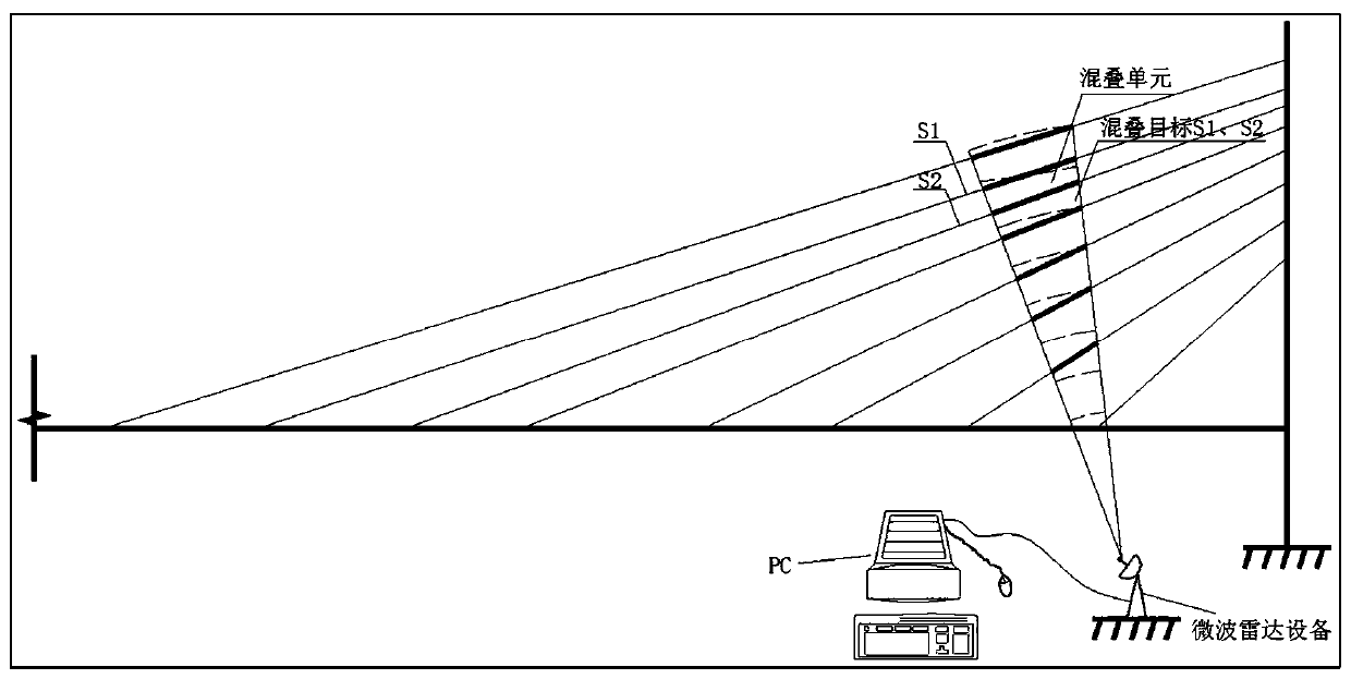
[0067] Taking a cable-stayed bridge cable group in a certain place as an example to illustrate the specific implementation process of the present invention. The stay cables of this cable-stayed bridge adopt 1860MPa steel strand stay cables, and 36 stay cables of different lengths are arranged in the whole bridge, and the feasibility of the present invention is verified by monitoring 8 stay cables on one side of the span of the cable-stay bridge .

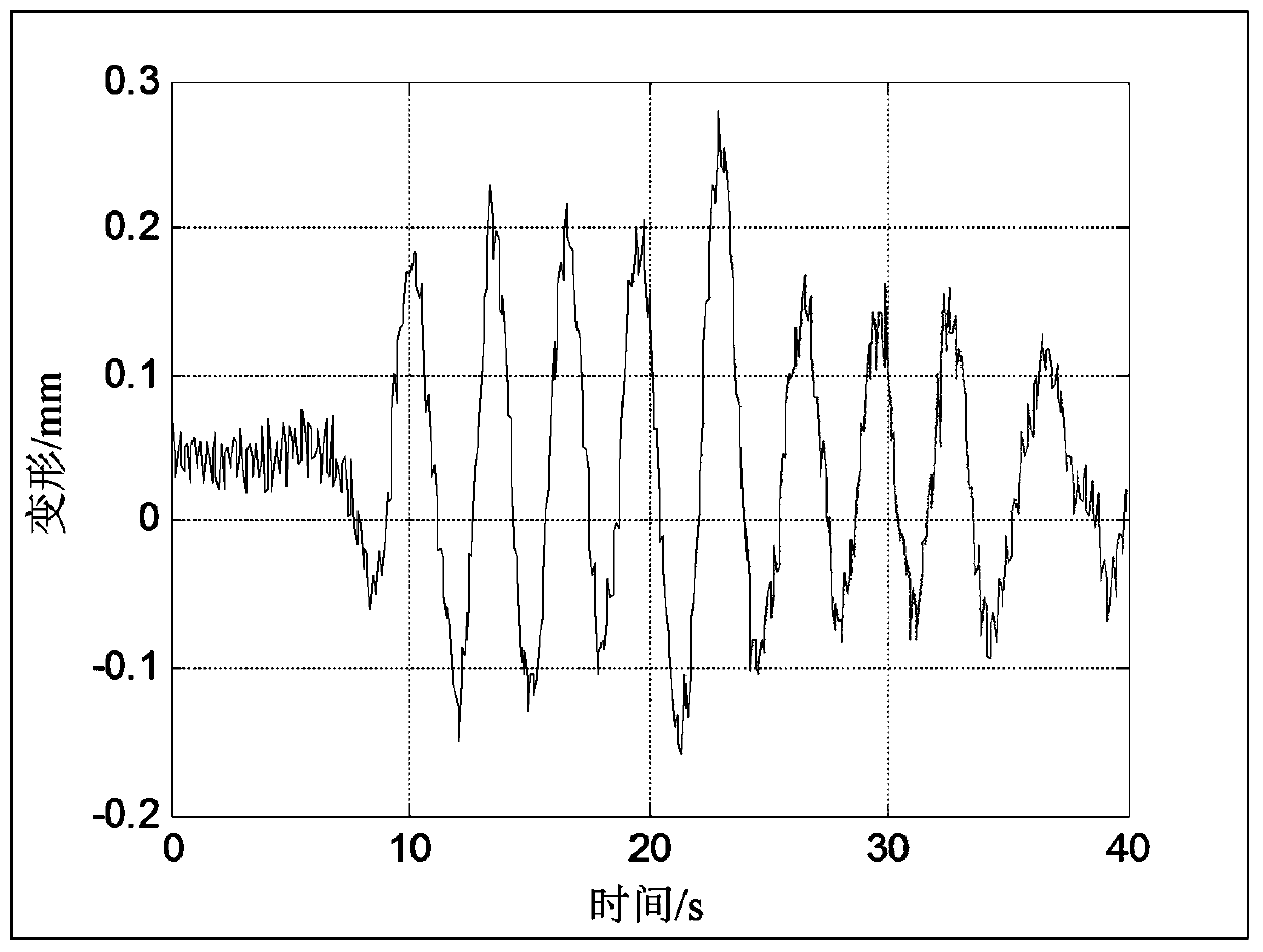
[0068] Step 1: The microwave radar equipment irradiates the cable group to be observed at a certain pitch angle, collects the orthogonal I / Q dual-channel zero-IF signal of each distance unit, and samples the orthogonal I / Q dual-channel zero-IF signal, as shown in Figure 6 (a) and (b) in the figure show the sampling signal of a certain distance unit. By comparing the phases of the sampling signals of each distance unit, the phase difference and deformation of each distance unit can be obtained, as shown in Figure 7 In (a) and (b) ...


PUM


Abstract

The invention discloses a bridge inhaul cable group cable force synchronous monitoring method and system based on a microwave radar. The system is mainly composed of the microwave radar equipment anda PC, wherein the microwave radar equipment internally emits a microwave signal to a bridge inhaul cable group and receives a reflected echo signal of the inhaul cable group, the echo signal is converted into an inhaul cable group micro time-process signal through a data processor, a display unit of the PC displays the inhaul cable group micro time-process signal, a time-process data analysis unitreads the inhaul cable group micro time-process signal, time-process signals of multiple cables in each measurement unit are separated through an embedded underdetermined time-process signal blind source separation algorithm fusing VMD and time-frequency analysis, and a VMD algorithm is adopted to recognize time-varying cable force of each cable in the inhaul cable group. Through the synchronousmonitoring method and system, an inhaul cable group time-varying cable force measurement solution which is efficient, accurate, high in stability and high in adaptability is provided, the problems that measuring point selection is difficult and test efficiency is low during inhaul cable group cable force measurement are effectively solved, the requirement for evaluation of cable force of a broad range of cable-stayed bridges and suspension bridges is met, and the synchronous monitoring method and system have good engineering application prospects.

Description

technical field [0001] The invention relates to a method and system for synchronously monitoring cable forces of bridge cable groups based on microwave radar. Background technique [0002] Based on the fixed mathematical relationship between the natural vibration frequency of the cable and the cable force, when the natural vibration frequency of the cable is measured, the cable force can be calculated from the relationship between the natural vibration frequency of the cable and the cable force, so the vibration frequency method is Currently the most advantageous cable force test method, so the vibration frequency method is the most widely used in the actual cable force test. There are a large number of cables in long-span cable-stayed bridges. Considering economic benefits, monitoring sensors are generally arranged on only a few main cables, so it is impossible to obtain cable forces without sensors installed. When measuring, the accelerometer method is time-consuming and ...

Claims


Application Information

Patent Timeline
Patent Type & Authority Applications(China)
IPC IPC(8): G01S13/88G01L5/00
CPCG01S13/88G01L5/00
Inventor 张建张光伟赵文举
Owner SOUTHEAST UNIV
Why Eureka
Try Eureka