Camera calibration method and terminal

A camera calibration and camera technology, applied in the field of electronic information, can solve the problems of affecting calculation results, calculation errors of vanishing points, and inapplicability of monitoring scenes, etc., and achieve the effect of accurate calibration matrix

Active Publication Date: 2019-07-19
SANLI VIDEO FREQUENCY SCI & TECH SHENZHEN
View PDF9 Cites 4 Cited by
  • Summary
  • Abstract
  • Description
  • Claims
  • Application Information

AI Technical Summary

Problems solved by technology

[0004] In the existing technology, the main point is usually selected by default at the center of the video picture when performing camera calibration, but when corresponding to the real world, the main point may not necessarily fall in the center of the road, and it is not applicable to the monitoring scene where the main point is not in the center of the road
Moreover, some of the existing technologies use Hough transform to detect straight lines, and use the voting method to obtain the direction of the vanishing point, which may cause errors in the calculation of the vanishing point, which will seriously affect the final calculation result.

Method used


Image

  • Camera calibration method and terminal
  • Camera calibration method and terminal
  • Camera calibration method and terminal

Examples


Embodiment 1

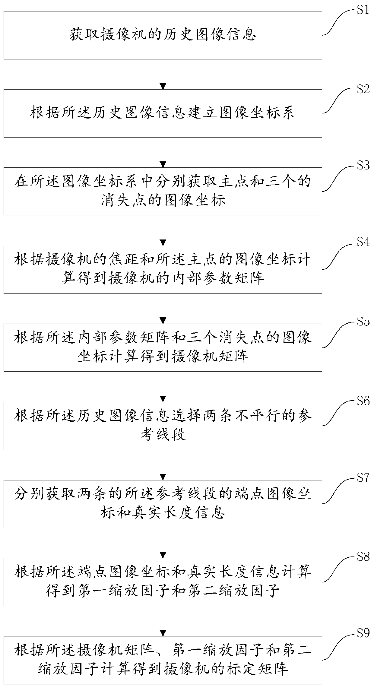
[0084] Please refer to figure 1 , Embodiment 1 of the present invention is: a camera calibration method, comprising the following steps:

[0085] S1. Obtain historical image information of the camera. In this embodiment, it is assumed that the image captured by the camera has no radial distortion, and the camera is looking straight ahead and downward. After the camera model is determined, its focal length is determined, assuming that the focal length of the camera is f.

[0086] S2. Establish an image coordinate system according to the historical image information. The coordinate origin of the image coordinate system can be set at the upper left corner of the picture, which can be a left-handed rectangular coordinate system or a right-handed rectangular coordinate system.

[0087] S3. Obtain the image coordinates of the main point and the three vanishing points respectively in the image coordinate system.

[0088] In this embodiment, before step S3, it further includes: re...

Embodiment 2

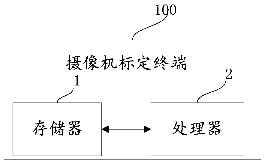
[0108] Please refer to figure 2 , Embodiment 2 of the present invention is: a camera calibration terminal 100, corresponding to the method of Embodiment 1, including a memory 1, a processor 2, and a computer stored in the memory 1 and operable on the processor 2 program, the processor 2 implements the following steps when executing the computer program:

[0109] Obtain the historical image information of the camera;

[0110] Establishing an image coordinate system according to the historical image information;

[0111] Obtaining the image coordinates of the principal point and the three vanishing points in the image coordinate system respectively;

[0112] calculating an internal parameter matrix of the camera according to the focal length of the camera and the image coordinates of the principal point;

[0113] calculating a camera matrix according to the internal parameter matrix and the image coordinates of the three vanishing points;

[0114] Selecting two non-parallel...


PUM


Abstract

The invention discloses a camera calibration method and a terminal. The method comprises the steps of obtaining historical image information of a camera; establishing an image coordinate system according to the historical image information; respectively acquiring image coordinates of the main point and the three vanishing points in the image coordinate system; performing calculating to obtain an internal parameter matrix of the camera according to the focal length of the camera and the image coordinates of the main point; performing calculating to obtain a camera matrix according to the internal parameter matrix and the image coordinates of the three vanishing points; selecting two non-parallel reference line segments according to the historical image information; respectively obtaining end point image coordinates and real length information of the two reference line segments; performing calculating to obtain a first scaling factor and a second scaling factor according to the end pointimage coordinates and the real length information; and performing calculating to obtain a calibration matrix of the camera according to the camera matrix, the first scaling factor and the second scaling factor. The calibration matrix is more accurate through calculation of the double scaling factors, and real information in a camera image can be accurately calculated.

Description

technical field [0001] The invention relates to the technical field of electronic information, in particular to a camera calibration method and a terminal. Background technique [0002] As the cost of cameras and processors continues to drop, vision-based sensing is becoming an alternative to traditional sensors for collecting traffic data. Many research and commercial systems have obtained a series of interesting information through video analysis, such as road occupancy, vehicle speed, vehicle type, and event detection. [0003] In order to measure information such as the speed of a vehicle based on the vision system, there must be a mapping from pixels in the image to world coordinates. The mapping relationship between the image coordinate system and the world coordinate system is defined by a series of internal and external parameters of the camera. Therefore, the camera must be calibrated, and the accuracy of the calibration will directly affect the final measurement r...

Claims


Application Information

Patent Timeline
Patent Type & Authority Applications(China)
IPC IPC(8): G06T7/80
CPCG06T7/80
Inventor 亢晓斌张宇刘东剑
Owner SANLI VIDEO FREQUENCY SCI & TECH SHENZHEN
Why Eureka
Try Eureka