Supercharge Your Innovation With Domain-Expert AI Agents!

Rotor for rotary electric machine

A technology for rotating electrical machines and rotors, applied in the field of rotors, which can solve problems such as the deformation of the connecting ribs of the rotor core, and achieve the effect of suppressing deformation

Active Publication Date: 2019-07-19
HONDA MOTOR CO LTD
View PDF9 Cites 0 Cited by
  • Summary
  • Abstract
  • Description
  • Claims
  • Application Information

AI Technical Summary

Problems solved by technology

Therefore, if there is a manufacturing error on the permanent magnet, when the rotor rotates at high speed, due to the centrifugal force of the permanent magnet, excessive stress will be generated in the circumferential center of the inner surface of the outer peripheral side of the magnet insertion hole, and the connecting rib of the rotor core may be damaged. will be deformed

Method used


Image

  • Rotor for rotary electric machine
  • Rotor for rotary electric machine
  • Rotor for rotary electric machine

Examples


no. 1 approach

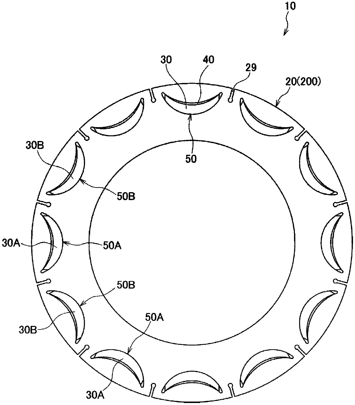
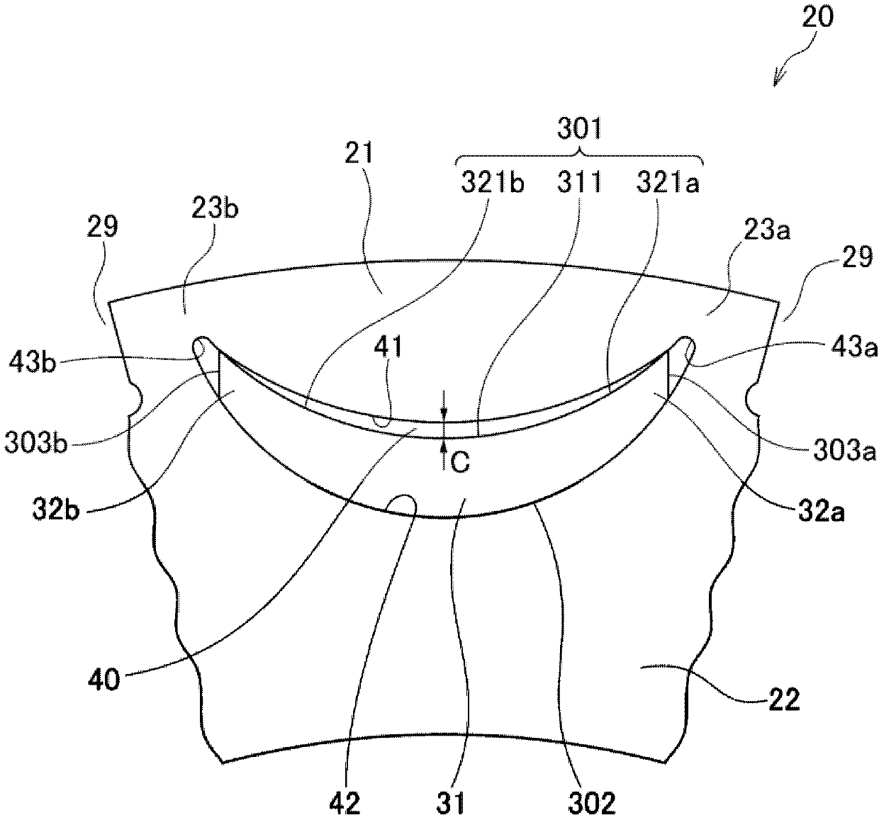
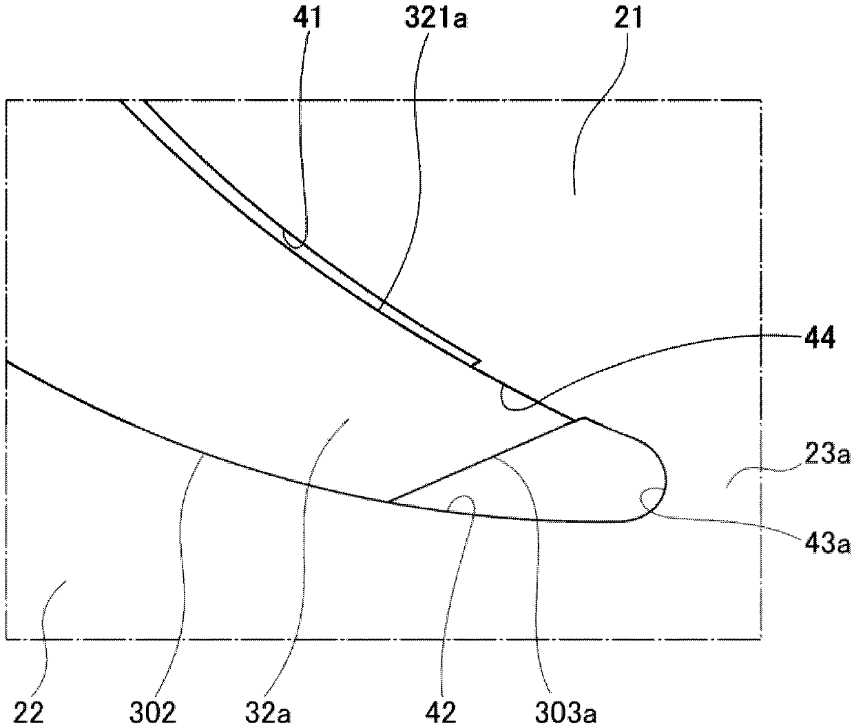
[0059] First, refer to Figure 1 ~ Figure 4 The rotor of the rotating electric machine according to the first embodiment of the present invention will be described.

[0060] Such as figure 1 As shown, the rotor 10 of the rotating electric machine according to the first embodiment includes a rotor core 20 attached to the outer peripheral portion of a rotor shaft (not shown), and a plurality of magnetic pole portions 50 formed at predetermined intervals in the circumferential direction inside the rotor core 20 , and the rotor 10 of the rotating electrical machine is disposed on the inner peripheral side of a stator (not shown).

[0061] The rotor core 20 is formed by stacking a plurality of annular electromagnetic steel sheets of substantially the same shape, for example, silicon steel sheets 200 in the axial direction, and has a plurality of magnet insertion holes 40 formed at predetermined intervals in the circumferential direction. In addition, a groove portion 29 is recess...


PUM


Abstract

A rotor for a rotary electric machine is provided and can avoid a situation that excessive stress is generated on the circumferential center portion of an outer-circumference-side inner surface of a magnet insertion hole during rotor rotation. The rotor (10) includes: a rotor core (20) which includes a magnet insertion hole (40); and a permanent magnet (30) housed in the magnet insertion hole. Thepermanent magnet has an arc shape which is convex toward an axial line. The rotor core includes: an outer-circumference core part (21); an inner-circumference core part (22); and connection ribs (23a, 23b) which connect the outer-circumference core part and the inner-circumference core part. The permanent magnet is supported in the rotor core in such a manner that circumferential ends abut on aninner surface of the magnet insertion hole. A circumferential center portion of the permanent magnet is separated from an outer-circumference-side inner surface of the magnet insertion hole. In the circumferential center portion, a gap is provided between an outer-circumference-side outer surface of the permanent magnet and the outer-circumference-side inner surface of the magnet insertion hole.

Description

technical field [0001] The present invention relates to a rotor mounted in a rotating electrical machine such as an electric vehicle. Background technique [0002] Conventionally, there is known a so-called IPM motor in which a plurality of permanent magnets are arranged at predetermined intervals in a circumferential direction inside a rotor core as a rotor used in a rotating electric machine. In such an IPM motor, arc-shaped permanent magnets are arranged so as to protrude toward the axis of rotation. As methods for fixing the arc-shaped permanent magnets to the rotor core, for example, patent documents 1 and 2 are known. documented technology. [0003] Patent Document 1 discloses a structure in which holes for riveting are provided on the outer peripheral side of the rotor, and the rotor core is deformed by pressing while riveting the rotor core with rivet pins, whereby the rotor core and the arc-shaped permanent magnet pass through the surface. contact for fixation. ...

Claims


Application Information

Patent Timeline
Patent Type & Authority Applications(China)
IPC IPC(8): H02K1/27
CPCH02K1/276H02K2213/03
Inventor 福井健太郎井上雅志
Owner HONDA MOTOR CO LTD
Features
  • R&D
  • Intellectual Property
  • Life Sciences
  • Materials
  • Tech Scout
  • Unparalleled Data Quality
  • Higher Quality Content
  • 60% Fewer Hallucinations
Learn More