Rinsing head and a rinser for gynaecology

A flushing head and flushing device technology, applied in the field of medical devices, can solve the problems of inconvenient cleaning of the vulva, vagina or fornix, inability to control the water outlet of the flushing head, and inconvenient replacement of the flushing head alone, so as to solve the problem of long drainage time and drainage Difficulty, effect of achieving a detachable connection

Pending Publication Date: 2019-07-23
SICHUAN CANCER HOSPITAL
View PDF1 Cites 7 Cited by
  • Summary
  • Abstract
  • Description
  • Claims
  • Application Information

AI Technical Summary

Problems solved by technology

[0004] The perineal irrigator in the prior art usually has some disadvantages. 1. It is not convenient to replace the rinsing head alone, and cross-infection is prone to occur. If the perineal irrigator is used once and then thrown away as a whole, it will cause waste of resources; 2. Clinically, when perineal irrigation is performed, the vulva, vagina, and fornix usually need to be rinsed separately. However, the existing perineal irrigation devices usually cannot control the water outlet of the irrigation head, which is not convenient for more accurate and efficient cleaning; For example, in a washer disclosed in Chinese patent CN208693897U, the rinse head is made of silica gel, which can effectively avoid damaging the inner wall of the vagina during the cleaning process. Water comes out from all directions of the head at the same time, which is not convenient for cleaning the vulva, vagina or fornix alone; 3. The existing perineal irrigators usually do not have the function of drainage, so that the perineal irrigators either need to be used in conjunction with the dilator, or need to be rinsed Repeatedly inserting and pulling out the vagina during the process can make the flushed sewage discharge from the vagina, so the existing perineal flushing device usually has the problem of difficult drainage during use

Method used


Image

  • Rinsing head and a rinser for gynaecology
  • Rinsing head and a rinser for gynaecology
  • Rinsing head and a rinser for gynaecology

Examples


Embodiment 1

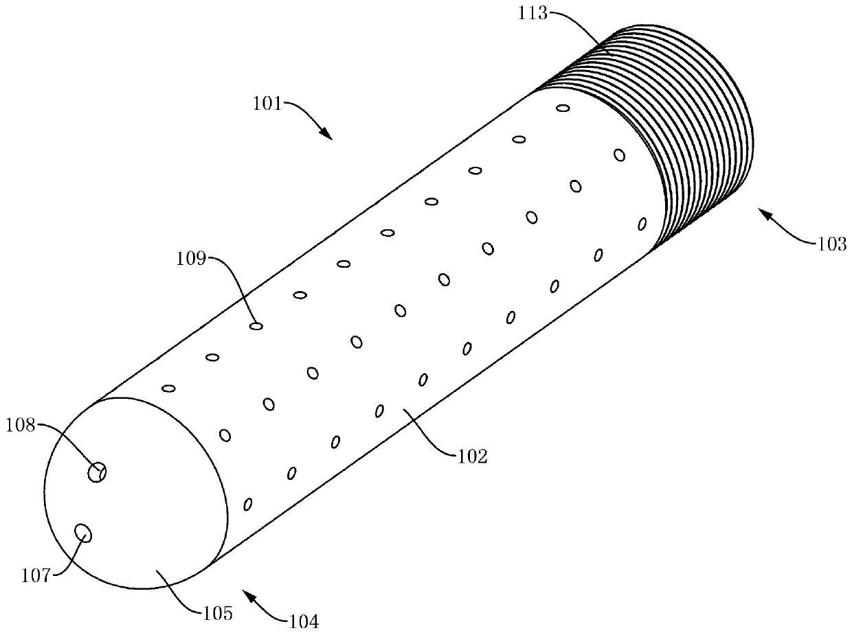
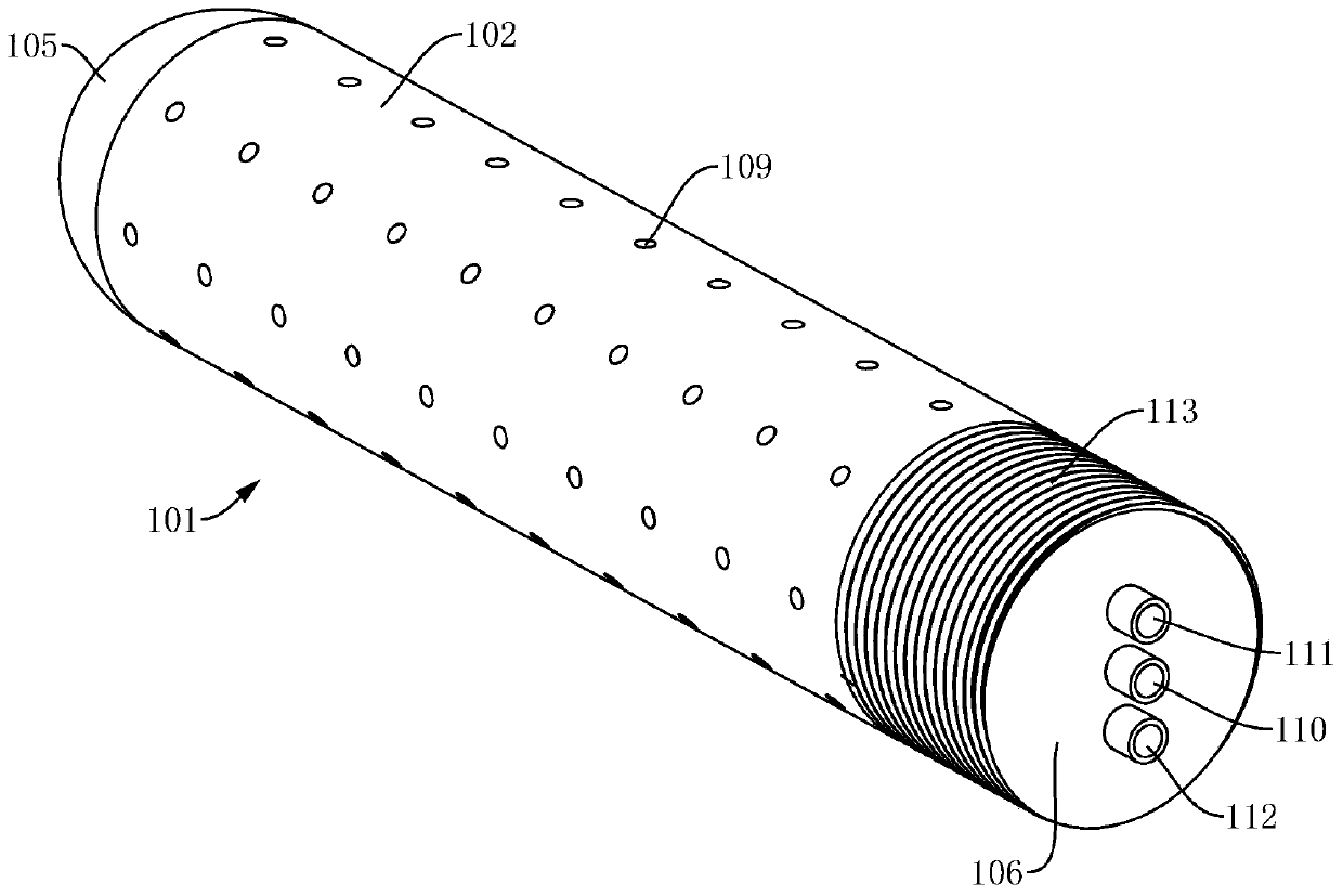
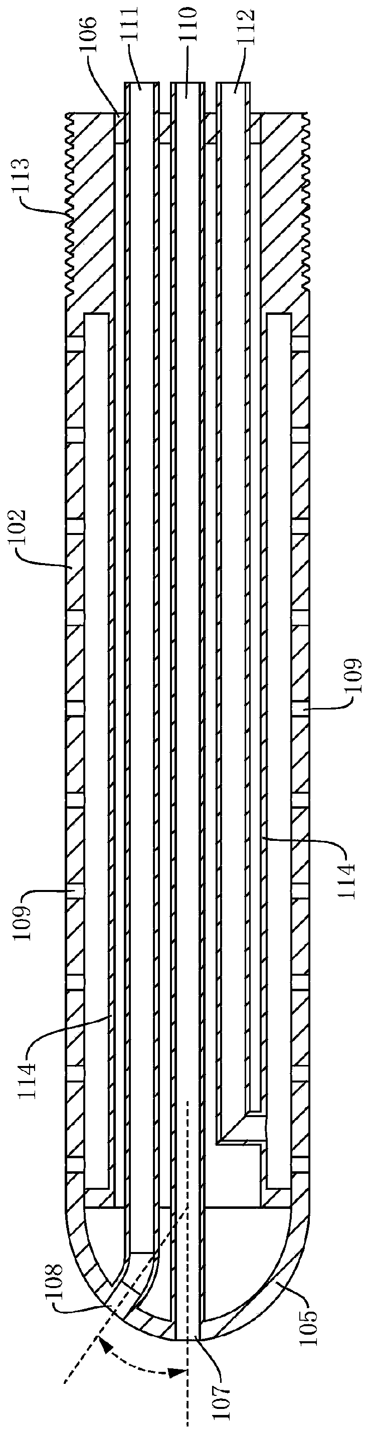
[0052] see figure 1 , figure 2 , image 3 , the embodiment provides a gynecological rinse head 101, including a rinse rod 102, the rinse rod 102 includes a first end 103 and a second end 104, the first end 103 is provided with a detachable Connected external thread 113, the second end 104 is set as an arc-shaped head 105, and the head is provided with a first water outlet 107 for flushing the vulva and a second water outlet 108 for flushing the fornix. The side wall of the rod 102 is provided with several third water outlets 109 for flushing the vagina, the second end 104 is provided with a partition 106 for closing the flushing rod 102, the first water outlet 107, the second water outlet 108 and the third water outlet 109 are respectively connected with the first passage 110, the second passage 111 and the third passage 112, and the first passage 110, the second passage 111 and the third passage 112 extend out of the partition 106 respectively, so as to be connected with t...

Embodiment 2

[0060] like Figure 10 and Figure 11 As shown, the present embodiment provides a flushing device, which includes a grip portion 201, a reversing portion 301 and the aforementioned flushing head 101. The flushing head 101 is connected to one end of the gripping portion 201 through a screw connection, and the end The first connection hole 202, the second connection hole 203 and the third connection hole 204 respectively used to connect the first channel 110, the second channel 111 and the third channel 112 are provided. Sealing cavity 205, the first connecting hole 202, the second connecting hole 203 and the third connecting hole 204 communicate with one side of the sealing cavity 205 respectively, such as Figure 5 and Image 6 As shown; the other side of the sealed cavity 205 communicates with the flow channel 206, and the flow channel 206 runs through the other end of the grip part 201, which end is provided with a connector 207 for connecting the infusion pipeline, and th...

Embodiment 3

[0071] When the patient uses the douche by himself, because he usually does not use a vaginal dilator, because the vaginal tissue has a strong contractility, when the douche head 101 is inserted into the vagina and flushes the vagina or fornix, the squeeze of the douche head 101 will The vagina is in an expanded state, and the vagina is in close contact with the flushing head 101, so that the sewage produced by flushing is not convenient to discharge from the vagina, so there is a problem of difficulty in drainage. Using the existing flushing device, it can be flushed with 500-1000 ml of water. During the process of flushing liquid, the patient needs to take out the flushing head 101 repeatedly, wait for the sewage in the vagina to discharge naturally, and then flush. The secretions washed out may not be able to be discharged smoothly from the vagina. In order to solve the problem of difficult drainage, the solution adopted in this embodiment is: the arc-shaped head is provide...


PUM

PropertyMeasurementUnit
Angleaaaaaaaaaa

Abstract

The invention relates to a rinsing head and a rinser for gynaecology. The rinsing head comprises a rinsing rod, wherein the rinsing rod comprises a first end and a second end; external threads for realizing detachable connection are arranged at the first end; the second end is an arc-shaped end socket; a first water outlet for rinsing vulvas and a second water outlet for rinsing fornix parts are formed in the end socket; a plurality of third water outlets for rinsing vaginas are formed in the side wall of the rinsing rod; a partition board for enclosing the rinsing rod is arranged at the second end; and the first water outlet is connected with a first channel, the second water outlet is connected with a second channel, and the third water outlets are connected with a third channel. The rinser provided by the invention is compact in structure, the rinsing head is convenient to replace, a user can conveniently control the direction of flushing liquid, conveniently rinse the vulvas, the vaginas and the fornix parts separately, and the rinser is very convenient; and in addition, the rinser can also effectively solve the problem that in the prior art, the drainage is difficult.

Description

technical field [0001] The invention relates to the technical field of medical devices, in particular to a gynecological flushing head and a flushing device. Background technique [0002] Today, many critically ill patients or patients suffering from perineal infectious diseases and gynecological operations need to clean and disinfect the perineum. In clinical practice, perineal irrigators are usually used for rinsing. [0003] At present, commonly used perineal irrigators usually include a rinsing head, a rinsing tube connected to the rinsing head, and a liquid storage device. When the gravity water is used for rinsing, the liquid storage device usually uses a rinsing bag, and the rinsing liquid is transported to the rinsing head through the rinsing pipe and sprayed out from the rinsing head to realize cleaning and disinfection. [0004] The perineal irrigator in the prior art usually has some disadvantages. 1. It is not convenient to replace the rinsing head alone, and cr...

Claims


Application Information

Patent Timeline
IPC IPC(8): A61M3/02A61H35/00
CPCA61M3/0279A61H35/00A61M2210/14A61M2210/1475A61H2205/087A61M2210/005
Inventor 肖雪李雪莲马丽田昌英何静
Owner SICHUAN CANCER HOSPITAL
Why Eureka
Try Eureka