Visual detection method of reflective circular ring piece

A technology for visual inspection and ring parts, applied in the field of visual inspection, can solve the problems affecting the operation efficiency and operation quality of visual inspection equipment, unfavorable for ordinary technicians to routinely change parameters, and complex algorithm steps, so as to reduce hardware configuration requirements and ensure Detect the effect of recognition quality, guarantee accuracy and stability

Inactive Publication Date: 2019-07-23
东莞中科蓝海智能视觉科技有限公司
View PDF13 Cites 3 Cited by
  • Summary
  • Abstract
  • Description
  • Claims
  • Application Information

AI Technical Summary

Problems solved by technology

[0003] As mentioned above, visual inspection has a huge market value. The core of the visual inspection system is not the hardware equipment but the algorithm steps, and the algorithm steps will vary depending on the requirements of the inspection results, product shape, working environment, and the technology of the designer or group. Factors such as ability vary widely. If the design of core algorithm steps is lacking, it will affect the operating efficiency and quality of the entire set of visual inspection equipment. In the algorithm steps of ring workpiece size inspection, indication defect inspection and thickness inspection, most of the algorithms on the market are The use cost of some technical solutions is high, and the algorithm steps are also relatively complicated, which is not conducive to the general technical personnel to routinely change parameters and other operation settings

Method used


Image

  • Visual detection method of reflective circular ring piece
  • Visual detection method of reflective circular ring piece

Examples


Embodiment Construction

[0017] In order to facilitate the understanding of those skilled in the art, the present invention will be further described below in conjunction with the examples, and the contents mentioned in the embodiments are not intended to limit the present invention.

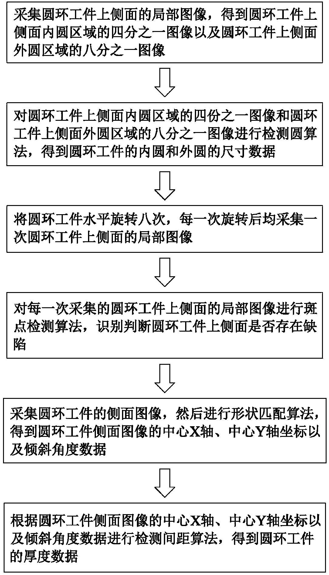
[0018] Such as figure 1 As shown, a visual detection method of a reflective circular ring includes the following steps: Step A: collecting a quarter of the image of the upper side of the circular ring workpiece, obtaining a quarter of the image of the inner circle area on the upper side of the circular ring workpiece and One-eighth image of the outer circle area on the side surface of the ring workpiece;

[0019] Step B: Perform a detection circle algorithm on the one-fourth image of the inner circle area on the side surface of the ring workpiece and the one-eighth image of the outer circle area on the side surface of the ring workpiece to obtain the dimensions of the inner circle and outer circle of the ring workpiece ...


PUM


Abstract

The invention relates to the technical field of visual detection, in particular to a visual detection method of a reflective circular ring piece. The visual detection method comprises the following steps that a quarter image of the upper side surface of the circular ring workpiece is collected; a circle detection algorithm is detected on the quarter image of the inner circle area and an eighth image of the outer circle area of the upper side surface of the circular ring workpiece to obtain size data of an inner circle and an outer circle of the circular ring workpiece; the circular ring workpiece is horizontally rotated for M times, and a local image on the upper side surface of the circular ring workpiece is collected once after rotation each time; and a spot detection algorithm is carried out on the local image on the upper side surface of the circular ring workpiece collected every time, and whether the defects exist on the upper side surface of the circular ring workpiece or not isidentified and judged. The multiple rotating shooting mode is adopted, and algorithm parameter setting which is accumulated by a manufacturer for a plurality of years is adopted, so that the accuracyand the stability of image detection and the identified data are effectively ensured, the use cost is reduced, and meanwhile, the detection and identification quality is ensured.

Description

technical field [0001] The invention relates to the technical field of visual inspection, in particular to a visual inspection method for a reflective circular ring. Background technique [0002] The feature of machine vision inspection is to improve the flexibility and automation of production. In some dangerous working environments that are not suitable for manual work or where artificial vision is difficult to meet the requirements, machine vision is often used to replace artificial vision; at the same time, in the process of mass industrial production, the efficiency and accuracy of using artificial vision to check product quality is low. , the use of machine vision inspection methods can greatly improve production efficiency and production automation. Moreover, machine vision is easy to realize information integration, and it is the basic technology to realize computer integrated manufacturing. Visual inspection is to use machines instead of human eyes for measurement...

Claims


Application Information

Patent Timeline
Patent Type & Authority Applications(China)
IPC IPC(8): B07C5/342B07C5/10
CPCB07C5/10B07C5/3422
Inventor 李清顺谭良
Owner 东莞中科蓝海智能视觉科技有限公司
Why Eureka
Try Eureka