
An assembly method of a detachable punching upper die set

An assembly method and module technology, which are applied in the direction of perforation tools, metal processing equipment, manufacturing tools, etc., can solve the problems of high use cost of integral forming punches, asynchronous replacement of multiple punches, etc. Avoid hard-to-remove effects

Active Publication Date: 2020-06-09
安徽恒兴装备材料有限公司
View PDF1 Cites 0 Cited by
  • Summary
  • Abstract
  • Description
  • Claims
  • Application Information

AI Technical Summary

Problems solved by technology

[0005] Aiming at the problems of high cost of using the integrally formed punch in the punching upper die set of the prior art, and the easy damage of the lateral fastening of the detachable punch, which causes asynchronous replacement of multiple punches, the present invention provides a detachable punching upper die set. The assembly method of the module, the working end of the punch is detachable and vertically fastened to the bottom of the punch base through the fastening mechanism, which avoids the horizontal fastening of the punch, is easy to disassemble and has a long service life

Method used


Image

  • An assembly method of a detachable punching upper die set
  • An assembly method of a detachable punching upper die set
  • An assembly method of a detachable punching upper die set

Examples


Embodiment 1

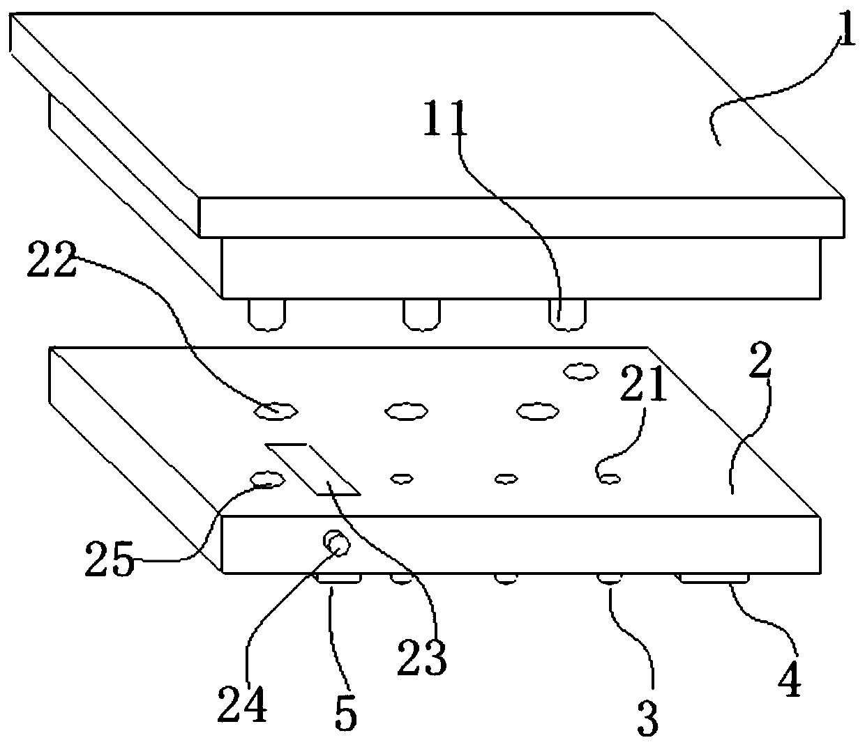
[0069] A kind of detachable punching upper die group of this embodiment, such as figure 1 , 6 As shown, it includes a fixedly connected upper mold base 1, an upper template 2, and a punch die embedded in the upper template 2, which passes downwards through the upper template 2, and a punching knife block 4 fixedly connected to the bottom end surface of the upper template 2 , the punch die is a detachable punch die 3, such as Figure 11 As shown, the detachable punch die 3 includes a punch base 31, a fastening mechanism 32 and a punch working end 33, such as Figure 12 As shown, the bottom of the punch base 31 is provided with a connecting head 311; as Figure 13 As shown, the fastening mechanism 32 has a sleeve-like structure, including a half-sealed connection sleeve 321 at one end and a punch hole 322 opened in the middle of the sealing end of the connection sleeve 321; The punch seat 332 and the punch end 331 connected together in an inverted "convex" shape; the upper t...

Embodiment 2

[0076] The basic steps of the assembly steps of a detachable punching upper die set in this embodiment are the same as in Embodiment 1, the difference and improvement is that in step 2, when the detachable fastening connection is made, the upper end of the punch seat 332 is pressed against When the bottom end of the connector 311 is punched, the punch end one 331 directly transmits the vertical pressure to the connector 311 through the punch seat 332, which will not affect the detachable connection between the connector sleeve 321 and the connector 311. It does not affect the convenient and easy disassembly between the connecting sleeve 321 and the connecting head 311 at any time.

Embodiment 3

[0078] A detachable punching upper die set in this embodiment has the same basic structure as that in Embodiment 1 or 2. The difference and improvement are that the connecting sleeve 321 and the connecting head 311 are threaded, and the connecting sleeve 321 is an internal thread. The connecting head 311 is an external thread; the second step is to screw the connecting sleeve 321 on the connecting head 311. Compared with detachable methods such as clamping and hinged connection, the threaded connection operation is more convenient.


PUM


Abstract

The invention discloses an assembling method for a detachable punching upper die set and relates to the field of material punching machining production. The assembling steps of the detachable punchingupper die set include that firstly, sleeving connecting is conducted, wherein a first punch end penetrates out of a punch through hole, and a punch seat is reserved in a connecting sleeve; secondly,fastening is conducted, wherein the connecting sleeve and a connecting head are detachably fastened and connected into a detachable punch die; thirdly, assembling is conducted, wherein the detachablepunch die penetrates out of a first punch hole, a punch work end downwards penetrates out of an upper die plate, and then a punch base is embedded in the first punch hole; and fourthly, fixing is conducted, wherein the upper die plate is fixedly connected to the bottom of an upper die seat, and the punch base is tightly attached to the bottom end face of the upper die seat. By means of the assembling method, the punch work end can be detachably and vertically fastened to the bottom of the punch base through a fastening mechanism, due to the fact that the punching direction is basically downward, vertical fastening is conducted, and the punching shearing force of transverse fastening is avoided; and the punch work end can be replaced at any time, the whole detachable punch die does not needto be replaced, and raw material cost is saved.

Description

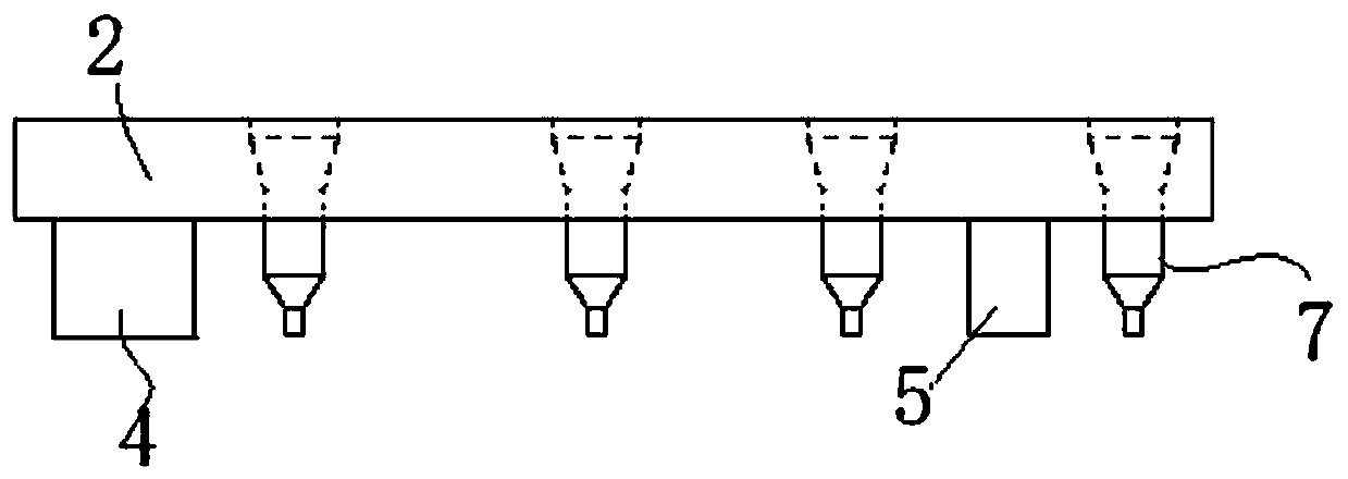
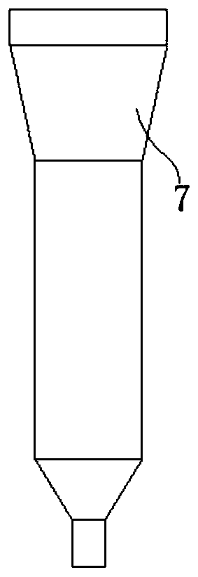
technical field [0001] The invention relates to the field of material punching processing and production, in particular to an assembly method of a detachable punching upper die set. Background technique [0002] Existing panel structures such as Figure 4 The steel frame plate used for the high-speed rail sound barrier shown needs to be trimmed and punched, such as figure 2 As shown, in the current punching upper die set for edge trimming and punching, punching dies of various shapes and specifications are sometimes required, such as edge punching knife block (4), square hole punching knife block (5) and punching dies of various shapes and specifications. The punch, and the punch seat and the punch end of the punch adopt such as image 3 The one-piece punch (7) shown in the picture, after long-term use, the punch end is gradually consumed due to wear, and finally the punch end cannot be used because it is damaged and scrapped. Since the punch end and the punch seat cannot ...

Claims


Application Information

Patent Timeline
Patent Type & Authority Patents(China)
IPC IPC(8): B21D28/34
CPCB21D28/34
Inventor 汪国华童效玲
Owner 安徽恒兴装备材料有限公司
Learn More