Rapid adjustable tip

An adjustable, top-notch technology, applied in the direction of tailstock/top, turning equipment, tool holder accessories, etc., can solve the problems of low production efficiency, time-consuming adjustment of the coaxiality of the thimble and the mandrel, etc., and achieves easy cleaning and shortening. effect of time

Inactive Publication Date: 2019-07-23
CHONGQING HONGGANG CNC MACHINE TOOL
View PDF8 Cites 4 Cited by
  • Summary
  • Abstract
  • Description
  • Claims
  • Application Information

AI Technical Summary

Problems solved by technology

[0005] The present invention provides a quick-adjustable tip to solve the problem of low production efficiency caused by the time-consuming adjustment of the coaxiality between the thimble and the mandrel in the prior art

Method used


Image

  • Rapid adjustable tip
  • Rapid adjustable tip
  • Rapid adjustable tip

Examples


Embodiment 1

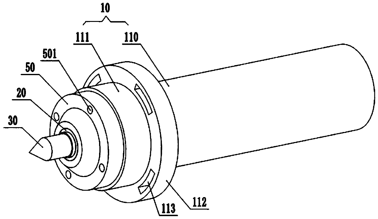
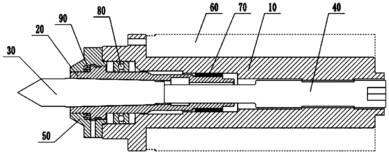
[0038] Embodiment 1 is basically as attached figure 1 and figure 2 Shown:

[0039] A quick-adjustable center, including a sleeve 10, a mandrel 20, a thimble 30, a push rod 40 and a sealing cover 50, the sleeve 10 is used to connect with the outer cylinder 60 on the tailstock of the machine tool, and the mandrel 20 is rotatably connected to the sleeve Inside the cylinder 10, the thimble 30 fits with the inner taper of the mandrel 20, and the ejector rod 40 includes a pressing section and a threaded section, wherein the threaded section is threaded with the inside of the sleeve 10, and the left end of the pressing section is pressed against the right end of the thimble 30 . The specific structure and assembly method of the sleeve 10, the mandrel 20, the ejector rod 40 and the sealing cover 50 are as follows:

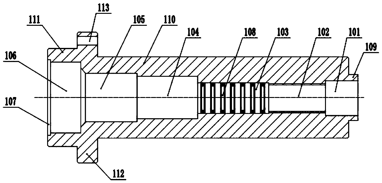
[0040] combine image 3 As shown, a guide hole 101, a threaded hole 102, an eccentric hole 103, a bearing installation hole 104, a mandrel passing hole 105, a positio...

Embodiment 2

[0051] Embodiment 2 is basically as attached figure 1 and Figure 5 Shown:

[0052] The difference between Embodiment 2 and Embodiment 1 is that a support mechanism is provided on the inner wall of the support hole 209, the support structure includes a plurality of strip-shaped airbags 1, and each airbag 1 is bonded to form a columnar tube, and the columnar tube is connected to the support hole. 209 coaxial, when the push rod 40 stretched into the support hole 209, the side wall of the push rod 40 extruded the airbag 1, as Figure 6 As shown, in each airbag 1, along the radial direction of the cylindrical tube, the support spring 11 is fixed, and the left end of the airbag 1 is provided with an exhaust check valve 12, and the right end of the airbag 1 is provided with an intake check valve 13; 1 When the squeezed internal volume decreases, the exhaust check valve 12 opens, and the gas inside the airbag 1 is discharged, and when the airbag 1 resumes deformation and the volume...


PUM


Abstract

The invention relates to the technical field of machine tool components, and particularly discloses a rapid adjustable tip. A sleeve, a core shaft, an ejector pin and an ejector rod are included. A threaded hole, a bearing installing hole and a positioning hole are sequentially in communication in the sleeve in the axial direction of the sleeve. The threaded hole is eccentric relative to the middle axis of the sleeve. The bearing installing hole, the positioning hole and the sleeve are coaxially arranged. The core shaft is rotationally connected in the bearing installing hole and the positioning hole. A conical hole, a middle hole and a supporting hole are sequentially in communication in the core shaft. The conical hole, the supporting hole and the core shaft are coaxially arranged. The middle hole is eccentrically arranged. The ejector pin is matched with the conical hole in taper. The ejector rod is in threaded connection with the threaded hole, and one end of the ejector rod tightly abuts against the tail of the ejector pin. By adoption of the technical scheme, the problems that in the prior art, the tip adjusting consumed time is long, and consequently the production efficiency is low are solved.

Description

technical field [0001] The invention relates to the technical field of machine tool components, in particular to a quick-adjustable center point. Background technique [0002] The top plays the role of positioning support for the workpiece during the machining process. The commonly used top is usually composed of a thimble, a clamping device, a housing, a fixed pin and a mandrel, and the tail of the thimble is matched with the taper of the mandrel, and the top is assembled during assembly. On the tailstock of the machine bed, and the tailstock can slide on the machine bed. [0003] In the machining process, it is usually necessary to adjust the tip. The main reason for this situation is that the thimble is matched with the taper of the mandrel, and impurities such as external coolant and metal dust will enter the taper fit during the machining process. The inclined surface causes greater wear between the thimble and the mandrel. Therefore, after the center has been in servi...

Claims


Application Information

Patent Timeline
Patent Type & Authority Applications(China)
IPC IPC(8): B23B23/04
CPCB23B23/045
Inventor 汪传宏
Owner CHONGQING HONGGANG CNC MACHINE TOOL
Why Eureka
Try Eureka