Continuous type station positioning device for multi-station polishing machine

A positioning device and multi-station technology, which is applied in the direction of grinding/polishing equipment, manufacturing tools, grinding workpiece supports, etc., can solve the problems that the positioning device cannot be accurately sensed, the station disc is misplaced, and the workpiece is easily damaged. Achieve the effect of reliable induction, accurate stop position and precise positioning

Active Publication Date: 2019-07-23
宇晶机器(长沙)有限公司
View PDF6 Cites 1 Cited by
  • Summary
  • Abstract
  • Description
  • Claims
  • Application Information

AI Technical Summary

Problems solved by technology

[0002] At present, a traditional single-station polishing equipment can only be used for the processing of one process. When the process is changed, the workpiece needs to be changed from one device to another, which wastes a lot of time and is easy to load and unload the workpiece. Damage to the workpiece; with the application of continuous multi-station polishing equipment, not only the processing efficiency of the equipment is

Method used


Image

  • Continuous type station positioning device for multi-station polishing machine
  • Continuous type station positioning device for multi-station polishing machine
  • Continuous type station positioning device for multi-station polishing machine

Examples


Embodiment

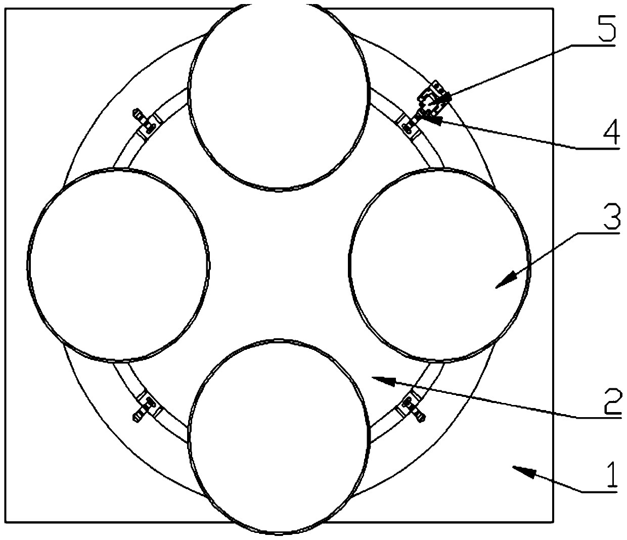
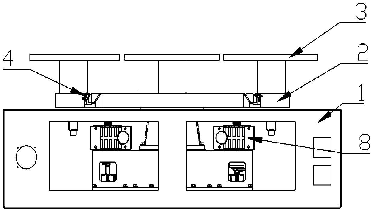
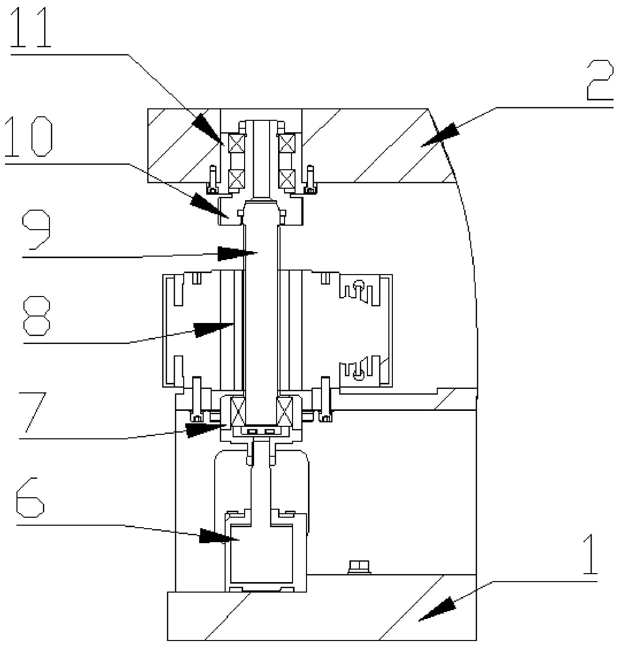
[0020] Referring to the attached drawings, a continuous multi-station polishing machine station positioning device includes a box body 1, a rotating platform 2, a station unit 3, a stroke striker 4, a multi-link stroke switch 5, a positioning cylinder 6, a lifting movable seat 7. Geared motor 8, spline shaft 9, gear shaft 10 and bearing seat 11; the number of the station units 3 are 4, and they are installed on the rotating platform 2 by screws; the multiple travel switch 5 is installed by screws On the box 1, the stroke bumps 4 are four, which are installed at different heights of the rotating platform 2 by screws evenly distributed, and are aligned horizontally with the different sensing points of the multiple travel switch 5. When the stroke bumps 4 When aligning with the multi-link travel switch 5, the corresponding station unit 3 is located directly in front of the machine; the positioning cylinder 6 and the geared motor 8 are both installed on the box 1 by screws, and the ...


PUM


Abstract

The invention discloses a continuous type station positioning device for a multi-station polishing machine. The continuous type station positioning device comprises a box body, a rotary platform, station units, and is equipped with stroke collision blocks, a multi-union stroke switch, a positioning gas cylinder, a lifting movable base, a reduction motor, a spline shaft, a gear shaft and a bearingbase, wherein the multi-union stroke switch is mounted on the box body; number of the stroke collision blocks is same with that of the station units; the stroke collision blocks are uniformly distributed and mounted on different height positions of the rotary platform, and are horizontally aligned to different induction points of the multi-union stroke switch; when the stroke collision blocks arealigned to the multi-union stroke switch, the corresponding station units are positioned in front of the machine; a piston rod the positioning gas cylinder is concentric with the output shaft of the reduction motor; the piston rod of the positioning gas cylinder is fixedly connected to the lifting movable base; the spline shaft passes through the reduction motor; the lower end of the spline shaftis mounted in the lifting movable base through a bearing; the gear shaft is mounted in the bearing base through a bearing; and when the stroke collision blocks are aligned to the multi-union stroke switch, the gear shaft is aligned to the spline shaft. The continuous type station positioning device has the advantages of being reliable in induction, precise in positioning, simple in structure, andthe like.

Description

Technical field [0001] The invention belongs to a continuous multi-station polishing equipment, and particularly relates to a continuous multi-station polishing equipment station positioning device. Background technique [0002] At present, a traditional single-station polishing equipment can only be used for the processing of one process. When the process is changed, the workpiece needs to be changed from one device to another. This wastes a lot of time and is easy to load and unload the workpiece. Damage to the workpiece; with the application of continuous multi-station polishing equipment, not only the processing efficiency of the equipment is improved, but also the realization of automatic control is more conducive. However, the station position detection and positioning device of the existing continuous multi-station polishing equipment cannot accurately sense it, resulting in the dislocation of the station plate, and the positioning block is located on the periphery of the ...

Claims


Application Information

Patent Timeline
IPC IPC(8): B24B27/00B24B41/00B24B41/06
CPCB24B27/0023B24B41/00B24B41/06
Inventor 杨佳葳蒋罗雄李红春
Owner 宇晶机器(长沙)有限公司
Why Eureka
Try Eureka