
Electric spiral slot puncher

A technology of electric screw punching machine, which is applied in the field of electric screw punching machine, can solve the problems of inaccurate stop position of the punch head, inconvenient picking and placing of slices, and many transmission parts, etc., to achieve extended life, compact structure, and easy operation. The effect of process smoothing

Inactive Publication Date: 2013-04-17
WUHU ELECTROTECHN MACHINERY
View PDF2 Cites 1 Cited by
  • Summary
  • Abstract
  • Description
  • Claims
  • Application Information

AI Technical Summary

Problems solved by technology

For the notching machine with this kind of notching motion system, the stop position of the punch (slider) is not accurate, and it is inconvenient to take and put the film; the notching noise is large
And because there are many transmission parts, the mechanism is complicated, the failure rate is high, and the reliability is low.

Method used


Image

  • Electric spiral slot puncher

Examples


Embodiment Construction

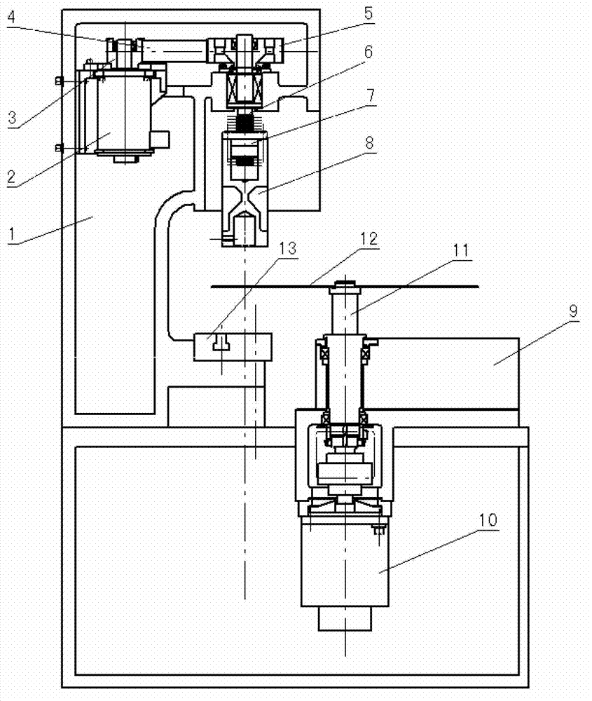
[0012] Such as figure 1 As shown, the electric spiral punching machine includes a fuselage 1, a slide block 8 is arranged on the fuselage 1, a servo motor 2 is installed on the top of the fuselage 1, and a small synchronous pulley 3 is installed on the output shaft of the servo motor 2, The small synchronous pulley 3 drives the large synchronous pulley 5 through the transmission of the synchronous belt 4, the large synchronous pulley 5 is equipped with a screw 6, the screw 6 rotates in the screw nut 7, and the screw nut 7 is fixed on the slider 8 The bottom of the fuselage 1 is equipped with an indexing device 9, and the indexing device 9 includes an indexing servo motor 10 and a vertical centering head 11 connected with the indexing servo motor 10, and an iron chip is installed on the upper end of the centering head 11 12. A workbench 13 facing the slider 8 is installed under the side of the core sheet 12.

[0013] The screw nut 7 converts the rotary motion of the screw rod ...


PUM


Abstract

The invention discloses an electric spiral slot puncher which comprises a body. A slider is arranged on the body. A servo motor is mounted at the top of the body. A small synchronous pulley is disposed on an output shaft of the servo motor and drives a large synchronous pulley through transmission of a synchronous belt. A screw is disposed on the large synchronous pulley and rotates in a screw nut. The screw nut is fixed on the slider. An indexing device is disposed below the body and comprises an indexing servo motor and a vertical centering head which is in drive connection with the indexing servo motor. A core lamination is disposed at the upper end of the centering head. A bench facing to a punch is disposed below the core lamination. The electric spiral slot puncher is compact in structure, high in flexibility, high in intelligence and smooth in operation. The position, speed and acceleration of the punch slider can be controlled, so that slotting noise is low, the service life of a punching die can be prolonged, impact and vibration of the puncher are reduced, and stop position of the punch slider is more accurate.

Description

technical field [0001] The invention relates to the field of slotting machines for motor iron chip processing equipment, in particular to an electric spiral slotting machine. Background technique [0002] The punching machine is a special equipment for single-slot punching used for punching the slot holes of the motor rotor or stator core. The punching die for punching the motor rotor or stator core sheet is installed between the punch (slider) and the worktable, and the upper die is driven to reciprocate up and down through the up and down reciprocating movement of the punch (slider). The iron chips (punches) that need to be punched are installed on the indexing device with intermittent movement, and the iron chips (punches) are rotated according to the preset requirements through the indexing device. When the punch (slider) moves downward, the iron chip (punch) does not rotate and waits for the punching groove. When the punch (slider) moves upward, the iron chip (...

Claims


Application Information

Patent Timeline
Patent Type & Authority Applications(China)
IPC IPC(8): B21D28/22B21D28/20
Inventor 单群来蒋万榆张玮王钟张登坪陈惟龙
Owner WUHU ELECTROTECHN MACHINERY
Learn More