I-shaped steel reinforced beam cantilevered scaffold

A technology of I-shaped steel beams and reinforced beams, which is applied to the accessories of scaffolding, scaffolding supported by house structures, and house structure supports, etc. Poor steel frame strength and other issues, to achieve the effect of reducing manufacturing and processing costs and construction costs, increasing use efficiency and practicability, and increasing stability and safety

Inactive Publication Date: 2019-07-23
SHENYANG JIANZHU UNIVERSITY
View PDF0 Cites 5 Cited by
  • Summary
  • Abstract
  • Description
  • Claims
  • Application Information

AI Technical Summary

Problems solved by technology

There were no specific industry regulations before, poor conditions in engineering work, large construction errors, etc., resulting in non-standard practice of cantilevered scaffolding and a serious decline in project quality
For example: 1. Two steel bars are welded horizontally on one side on site. After the cantilever beam is stressed, there is a small vertical displacement. The horizontal displacement of the cantilever beam is difficult to control. The on-site construction quality of the single-sided horizontal weld of two steel bars is not easy to control.
2. Reinforced with wooden wedges, the wooden wedges will be deformed after being stressed, and the strength of the welded cross bars and door-shaped steel frames is poor
3. A later linking method, the end is fixed by double channels, the wooden wedge is replaced by an iron wedge, and the two-way wedge is used, and there are pre-embedded residues and inconvenience in construction.

Method used


Image

  • I-shaped steel reinforced beam cantilevered scaffold
  • I-shaped steel reinforced beam cantilevered scaffold
  • I-shaped steel reinforced beam cantilevered scaffold

Examples


Embodiment

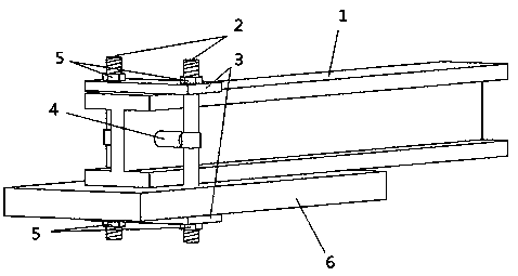
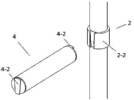
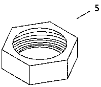
[0020] Such as Figure 1~Figure 4 As shown, a kind of I-beam reinforced beam cantilevered scaffold of the present invention comprises I-beam 1, vertical steel pipe 2, steel plate 3, horizontal steel pipe 4, nut 5, concrete floor slab 6, hollow plastic pipe 7, I-beam The steel beam 1 is placed on the concrete floor 6, and one end is protruded, and the protruded end is the head and the other end is the tail. There is a circular opening on the web plate at the tail of the I-shaped steel beam 1, and two steel plates 3 are respectively placed on the I-shaped steel beam. The upper part of the tail and the lower part of the concrete floor 6, the long side direction of the steel plate 3 is perpendicular to the long side direction of the I-shaped steel beam 1, the vertical direction of the two steel plates 3 corresponds vertically, and the length of the steel plate 3 is greater than the width of the flange plate of the I-shaped steel beam 1 , there are two circular through openings at ...


PUM


Abstract

The invention provides an I-shaped steel reinforced beam cantilevered scaffold, and belongs to the technical field of temporary buildings. The I-shaped steel reinforced beam cantilevered scaffold comprises a steel I-beam with a web at one end provided with a circular opening, a vertical steel pipe with rotating threads at both ends and a keyway type joint socket in the middle, steel plates with two circular openings, a horizontal steel pipe with keyway type joint plugs welded at both ends, nuts with internal rotating threads, and a concrete floor with pre-embedded parts. Vertical displacementis limited by the nuts, and horizontal displacement is limited by keyway type joints and the steel pipes. According to the I-shaped steel reinforced beam cantilevered scaffold, installation is convenient, recycling can be achieved, the stability and security of connection are improved, and meanwhile, the limitation of embedded residue on the space use function is reduced.

Description

technical field [0001] The invention belongs to the technical field of temporary buildings, in particular to an I-shaped steel reinforced beam cantilevered scaffold. Background technique [0002] Scaffolding collapse accidents in the construction industry are becoming more and more prominent. Suspended scaffolding is a commonly used scaffolding in engineering. It is a simple facility used in construction. It is divided into two types: one per floor and multi-layer cantilever. There were no specific industry regulations before, poor conditions in engineering work, large construction errors, etc., resulting in non-standard practices of cantilevered scaffolding and a serious decline in project quality. For example: 1. Two steel bars are welded horizontally on one side on site, there is a small vertical displacement of the cantilever beam after being stressed, the horizontal displacement of the cantilever beam is difficult to control, and the on-site construction quality of the...

Claims


Application Information

Patent Timeline
IPC IPC(8): E04G3/18E04G5/04
CPCE04G3/18E04G5/04E04G5/041
Inventor 张延年张意秦桂娟
Owner SHENYANG JIANZHU UNIVERSITY
Why Eureka
Try Eureka