Underwater constructed water sealing layer monitoring device for vertical shaft

A technology for monitoring devices and water layers, applied in construction and other directions, to achieve the effect of ensuring one-time success rate and improving reliability

Pending Publication Date: 2019-07-23
TONGLING ZHONGDU MINING CONSTR
View PDF0 Cites 0 Cited by
  • Summary
  • Abstract
  • Description
  • Claims
  • Application Information

AI Technical Summary

Problems solved by technology

[0003] The purpose of the present invention is to solve the problem that there is no real-time monitoring in the process of grouting to construct the water sealing layer in the prior art

Method used


Image

  • Underwater constructed water sealing layer monitoring device for vertical shaft
  • Underwater constructed water sealing layer monitoring device for vertical shaft
  • Underwater constructed water sealing layer monitoring device for vertical shaft

Examples


Embodiment 1

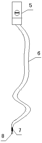
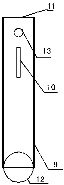
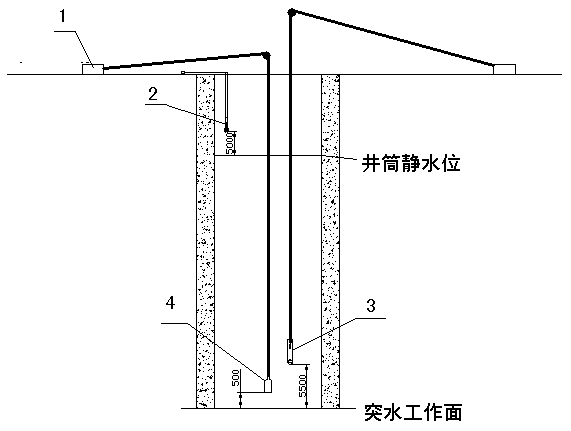
[0020] Embodiment 1: A vertical well underwater construction water sealing layer monitoring device, including a lifting device 1, a water level monitoring device 2, a slurry sampling device 3 and a deep well imager 4, there are several lifting devices, and the water level monitoring device includes a multimeter 5. Electric wire 6, insulating plate 7 and electrode tip 8, the electrode tip is installed on the insulating plate, one end of the electric wire is connected to the electrode tip through the insulating plate, and the other end is connected to the multimeter, and the slurry sampling device includes a tube body 9, The slurry inlet 10 and the sealing plate 11, the slurry inlet is arranged on the side wall of the pipe body, the sealing plate is connected with the pipe body, and there are several lifting devices connected with the deep well imager and the pipe body respectively.

Embodiment 2

[0021] The difference between embodiment 2 and embodiment 1 is that it also includes a solid sphere 12 and a suspension hole 13, the solid sphere is fixedly connected to the bottom of the pipe body, there is one sealing plate and the sealing plate is divided into two halves. It is connected to both sides of the top of the pipe body, at least half of which is movably connected to the top of the pipe body. The suspension hole is opened on the side wall of the pipe body and is located above the slurry inlet. One of the lifting devices is connected to the pipe body through the suspension hole.

[0022] Among the present invention, hoisting device can adopt the equipment such as stabilizing car, winch, winch etc. in the prior art. During the monitoring process of the water level monitoring device, when the electrode head touches the water surface, a loop is formed, and the number displayed by the multimeter changes at this time, and the water level in the wellbore can be calculated ...


PUM


Abstract

The invention discloses an underwater constructed water sealing layer monitoring device for a vertical shaft. The underwater constructed water sealing layer monitoring device comprises a plurality oflifting devices, a water level monitoring device, a grout sampling device and a deep well imager, the water level monitoring device comprises a multimeter, a wire, an insulation board and an electrodetip, the electrode tip is installed on the insulation board, one end of the wire penetrates through the insulation board and is connected with the electrode tip, and the other end of the wire is connected with the multimeter; and the grout sampling device comprises a tube body, a grout inlet port and a sealing plate, the grout inlet port is formed in the side wall of the tube body, the sealing plate is connected with the tube body, and the multiple lifting devices are connected with the deep well imager and the tube body correspondingly. Through the structure, the conditions of the grout height change in a wellbore, the rising height change of the water level, the grout change along with the filling amount and the like are monitored in the whole process, the one-time success rate of constructing a water sealing layer through grouting is ensured, and the reliability of constructing the water sealing layer is improved.

Description

technical field [0001] The invention relates to a monitoring device for a water sealing layer constructed underwater in a shaft. Background technique [0002] With the gradual increase in the depth of mining development at home and abroad, there are more and more vertical shaft projects, especially those with a depth of more than 1,000 meters, and the probability of water inrush and flooding is relatively increased. As the active and most effective method to control the disaster of vertical shaft water inrush and flooding, grouting construction of vertical shaft water inrush and flooding will be more and more applied in engineering practice. So far, in domestic and foreign technical research on vertical shaft grouting to construct a water-sealing layer to control water inrush and flooded wells, in terms of the control of grout injection volume, most of the grout injection volume is calculated according to construction experience. When the grout injection volume reaches the t...

Claims


Application Information

Patent Timeline
IPC IPC(8): E21B47/047E21B47/002
CPCE21B47/002E21B47/047
Inventor 班春燕罗姜方明唐燕林姚维林
Owner TONGLING ZHONGDU MINING CONSTR
Why Eureka
Try Eureka