
Lens coupling system and method

A coupling system and lens technology, applied in the coupling of optical waveguide, material gluing, light guide, etc., can solve the problems of high labor intensity, low efficiency and accuracy, and achieve the reduction of labor intensity, improvement of efficiency and accuracy, and degree of automation high effect

Pending Publication Date: 2019-07-23
CENT SOUTH UNIV +1
View PDF5 Cites 35 Cited by
  • Summary
  • Abstract
  • Description
  • Claims
  • Application Information

AI Technical Summary

Problems solved by technology

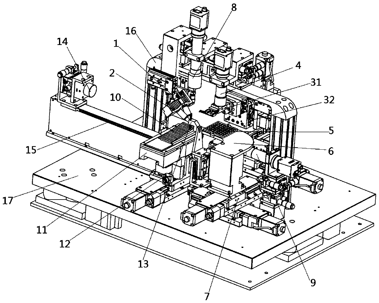
[0006] The purpose of the present invention is to provide a lens coupling system and method, which is used to solve or partly solve the problem that most of the existing lens coupling needs to manually attach the lens to the chip, the efficiency and accuracy are low, and the labor intensity is relatively large.

Method used


Image

  • Lens coupling system and method
  • Lens coupling system and method
  • Lens coupling system and method

Examples


Embodiment Construction

[0052] The specific implementation manners of the present invention will be further described in detail below in conjunction with the accompanying drawings and embodiments. The following examples are used to illustrate the present invention, but are not intended to limit the scope of the present invention.

[0053] In the description of the present invention, it should be noted that unless otherwise specified and limited, the terms "installation", "connection" and "connection" should be understood in a broad sense, for example, it can be a fixed connection or a detachable connection. Connected, or integrally connected; it can be mechanically connected or electrically connected; it can be directly connected or indirectly connected through an intermediary, and it can be the internal communication of two components. Those of ordinary skill in the art can understand the specific meanings of the above terms in the present invention in specific situations.

[0054] According to an ...


PUM


Abstract

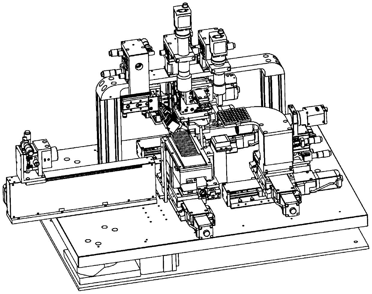
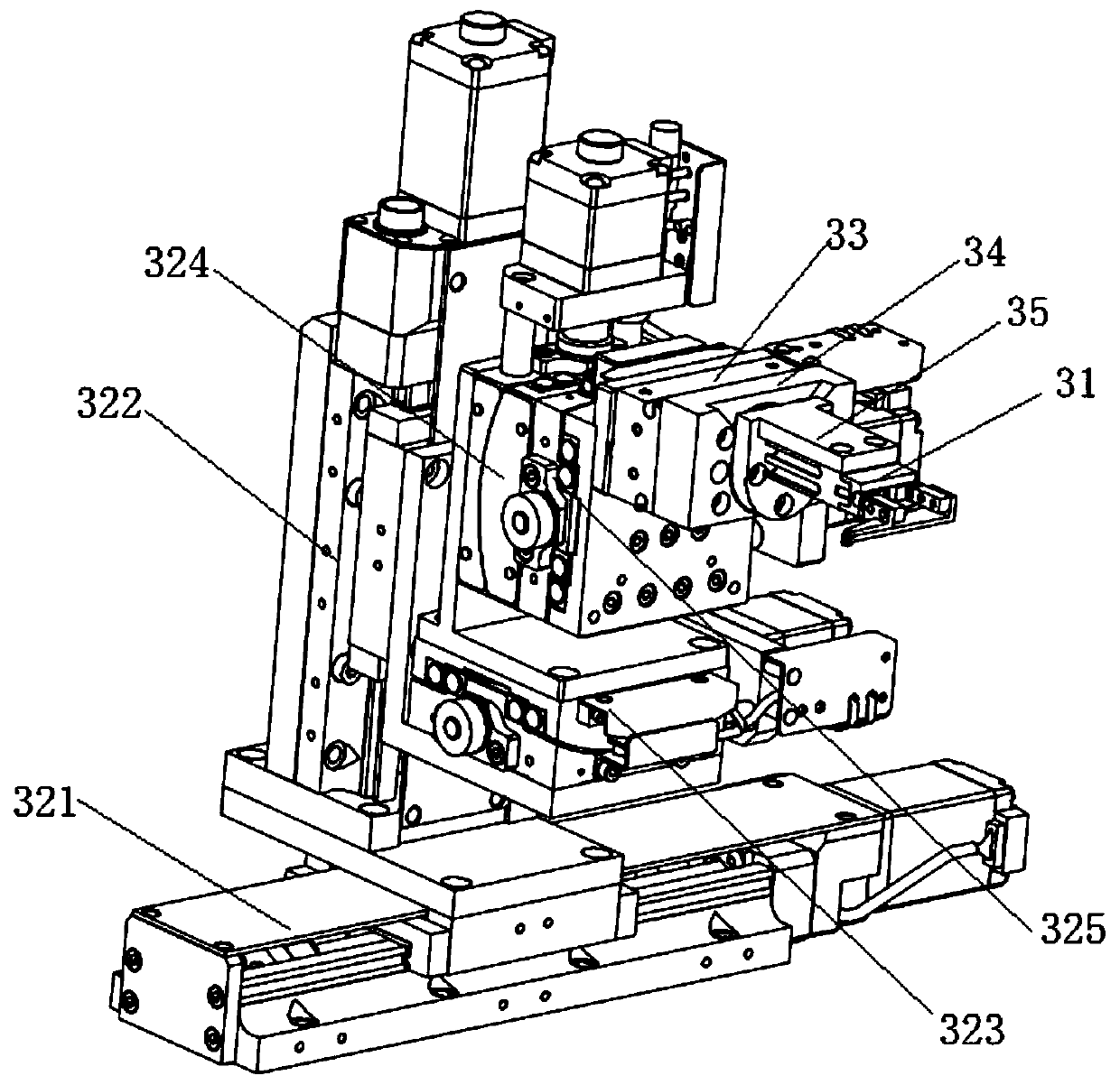
The invention relates to the field of optical device installation, and discloses a lens coupling system and method. The system comprises the following parts of a grasping mechanism for grasping a lensin a tray; a space displacement mechanism connected to the grasping mechanism for driving the lens to move to contact a dispensing mechanism for dispensing and for moving the dispensed lens to fit achip; a curing mechanism disposed above the chip for curing the glue between the lens and the chip; and a positioning subsystem comprising a first image detecting mechanism, which is disposed above the tray for obtaining position information of the lens in the tray. The lens coupling system and method provided by the invention can automatically couple the lens and the chip, and can obtain preciseposition information of the lens on the tray by providing the first image detecting mechanism, so that the grasping mechanism can smoothly and accurately grasp the lens. The system is highly automated, and can reduce labor intensity, position the lens and improve efficiency and accuracy.

Description

technical field [0001] The invention relates to the field of optical device installation, in particular to a lens coupling system and method. Background technique [0002] Semiconductor lasers are P-N junction diodes with optical feedback functions that use semiconductor materials as the working substance. Compared with solid-state lasers and gas lasers, they have the advantages of compact structure, high reliability, high efficiency and stability, and have been widely used in mechanical processing, materials, etc. industries such as processing, weapons manufacturing and laser display. Semiconductor lasers have special light-emitting characteristics, and the output laser light generally cannot be directly used in practice, and must be shaped, transformed and collimated. Therefore, since the birth of semiconductor lasers, the coupling problem of semiconductor lasers has arisen. The so-called coupling process is mainly to align the part with stronger light intensity in the c...

Claims


Application Information

Patent Timeline
Patent Type & Authority Applications(China)
IPC IPC(8): G02B6/42G02B6/32F16B11/00
CPCG02B6/4204G02B6/4239G02B6/4244G02B6/4296G02B6/32F16B11/006
Inventor 段吉安卢昆忠唐佳卢胜强徐聪苏文毅胡慧璇黄思琪
Owner CENT SOUTH UNIV
Learn More