Optical imaging lens

An optical imaging lens and imaging technology, applied in the field of lenses, can solve problems such as more loss of transfer function, inaccurate color reproduction, and reduced resolution, and achieve the effects of good infrared confocality, simple structure and high resolution

Pending Publication Date: 2019-07-23
XIAMEN LEADING OPTICS
View PDF0 Cites 5 Cited by
  • Summary
  • Abstract
  • Description
  • Claims
  • Application Information

AI Technical Summary

Problems solved by technology

When used in the field of security monitoring, optical imaging lenses usually work 24 hours a day without interruption. Therefore, the requirements for infrared confocal performance of optical imaging lenses are getting higher and higher, especially optical imaging lenses equipped with RGB-IR sensors. However, the current infrared confocal lens has a large amount of defocus when switching to visible infrared, and requires a switch or filter, which has a complex structure and high cost; when switching to infrared, the transfer function loses more and the resolution decreases; When it is visible, the chromatic aberration will be too large, the color reproduction is not accurate, and the relative illumination is relatively low, and the imaging quality is poor in a dark environment, which cannot meet the increasing requirements

Method used


Image

  • Optical imaging lens
  • Optical imaging lens
  • Optical imaging lens

Examples


Embodiment 2

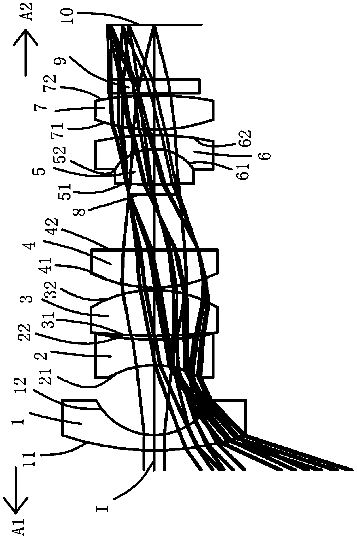
[0106] Such as Picture 9 As shown, the surface concave and convex and refractive power of each lens in this embodiment and the first embodiment are the same, and only the optical parameters such as the radius of curvature and the lens thickness of each lens surface are different. In order to show the structure of this embodiment more clearly, the same concave-convex surface type reference numerals are omitted.

[0107] The detailed optical data of this specific embodiment is shown in Table 2-1.

[0108] Table 2-1 Detailed optical data of Example 2

[0109]

[0110]

[0111] For the values ​​of the relevant conditional expressions of this specific embodiment, please refer to Figure 41 .

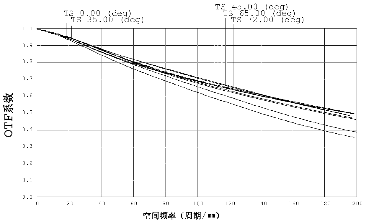
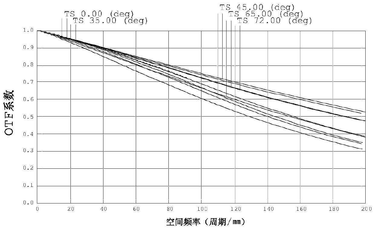
[0112] For the resolution of this specific embodiment, please refer to Picture 10 with 11 , It can be seen from the picture that the resolution is good when switching between infrared and visible environments, and the resolution is high. Please refer to the confocal between visible and infrared 85...

Embodiment 3

[0115] Such as Figure 17 As shown, the surface concave and convex and refractive power of each lens in this embodiment and the first embodiment are the same, and only the optical parameters such as the radius of curvature and the lens thickness of each lens surface are different. In order to show the structure of this embodiment more clearly, the same concave-convex surface type reference numerals are omitted.

[0116] The detailed optical data of this specific embodiment is shown in Table 3-1.

[0117] Table 3-1 Detailed optical data of Example 3

[0118]

[0119]

[0120] For the values ​​of the relevant conditional expressions of this specific embodiment, please refer to Figure 41 .

[0121] For the resolution of this specific embodiment, please refer to Figure 18 with 19 , It can be seen from the picture that the resolution is good when switching between infrared and visible environments, and the resolution is high. Please refer to the confocal between visible and infrared 850...

Embodiment 4

[0124] Such as Figure 25 As shown, the surface concave and convex and refractive power of each lens in this embodiment and the first embodiment are the same, and only the optical parameters such as the radius of curvature and the lens thickness of each lens surface are different. In order to show the structure of this embodiment more clearly, the same concave-convex surface type reference numerals are omitted.

[0125] The detailed optical data of this specific embodiment is shown in Table 4-1.

[0126] Table 4-1 Detailed optical data of Example 4

[0127]

[0128]

[0129] For the values ​​of the relevant conditional expressions of this specific embodiment, please refer to Figure 41 .

[0130] For the resolution of this specific embodiment, please refer to Figure 26 with 27 , It can be seen from the picture that the resolution is good when switching between infrared and visible environments, and the resolution is high. Please refer to the confocal between visible and infrared 850...


PUM


Abstract

The invention relates to the technical field of lenses. The invention discloses an optical imaging lens. The optical imaging lens sequentially comprises a first lens, a second lens, a third lens, a fourth lens, a diaphragm, a fifth lens, a sixth lens and a seventh lens from an object side to an image side along an optical axis, wherein the first lens is a convexo-concave lens with a negative refractive index; the second lens is a concave lens with the negative refractive index; the third lens is a convex lens with a positive refractive index; the fourth lens is a convexo-plane lens with the positive refractive index; the fifth lens is a convex lens with the positive refractive index; the sixth lens is a convexo-concave lens with the negative refractive index; and the seventh lens is a convex lens with the positive refractive index. The optical imaging lens has the advantages of being good in infrared confocal performance, high in resolution and small in color difference.

Description

Technical field [0001] The invention belongs to the field of lens technology, and specifically relates to an optical imaging lens with an RGB-IR sensor. Background technique [0002] With the continuous advancement of technology, in recent years, optical imaging lenses have also been rapidly developed and are widely used in various fields such as smart phones, tablet computers, video conferencing, vehicle monitoring, and security monitoring. When applied in the field of security monitoring, optical imaging lenses usually work uninterrupted 24 hours a day. Therefore, the infrared confocal requirements of optical imaging lenses are getting higher and higher, especially those equipped with RGB-IR sensors. However, the current infrared confocal lens has a large defocus when switching between visible and infrared, which requires a switch or filter, which has a complicated structure and high cost; when switching to infrared, the transfer function is lost more and the resolution is redu...

Claims


Application Information

Patent Timeline
Patent Type & Authority Applications(China)
IPC IPC(8): G02B13/00G02B13/14
CPCG02B13/0015G02B13/008G02B13/14
Inventor 张军光王世昌
Owner XIAMEN LEADING OPTICS
Why Eureka
Try Eureka