Rotating machinery shafting fatigue strength detection method

A technology of fatigue strength and rotating machinery, applied in computer-aided design, special data processing applications, instruments, etc., can solve problems such as lack of equipment and complex working environment, achieve strong application ability, improve efficiency, and simple and efficient testing process

Active Publication Date: 2019-07-23
SOUTHEAST UNIV
View PDF3 Cites 2 Cited by
  • Summary
  • Abstract
  • Description
  • Claims
  • Application Information

AI Technical Summary

Problems solved by technology

However, in specific tests, the working environment of auxiliary equipment and other equipment is generally more complicated,

Method used


Image

  • Rotating machinery shafting fatigue strength detection method
  • Rotating machinery shafting fatigue strength detection method
  • Rotating machinery shafting fatigue strength detection method

Examples


Embodiment 1

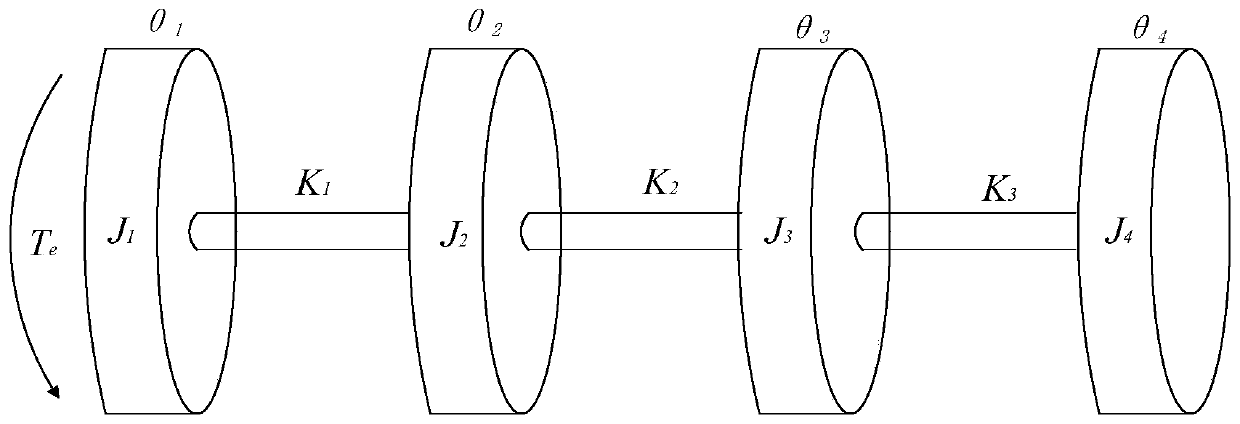
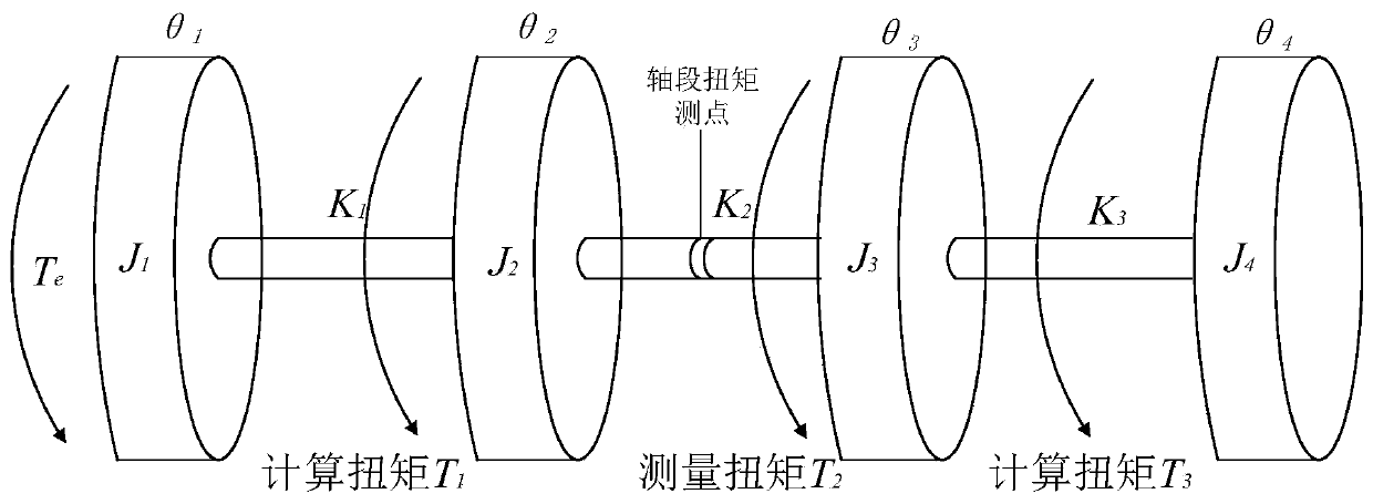
[0063]In this embodiment, a four-mass model is constructed, and only one measuring point is arranged at the second shaft section to calculate the stress distribution of each shaft section in order to detect the fatigue strength. Refer to Figure 1~3 , the specific method is as follows:

[0064] (1) Establish the analysis model of the four-mass block of the shaft system as follows: figure 1 shown in J 1 Torque T applied at the mass e . The moments of inertia of the four mass blocks in the figure are J 1 、J 2 、J 3 and J 4 , the torsional stiffness of the three shaft segments are K 1 、K 2 、K 3 , θ 1 , θ 2 , θ 3 , θ 4 represent the relative angular displacement of each segment, respectively. according to figure 1 The dynamic equation of the shaft system is established as follows:

[0065]

[0066] In the formula:

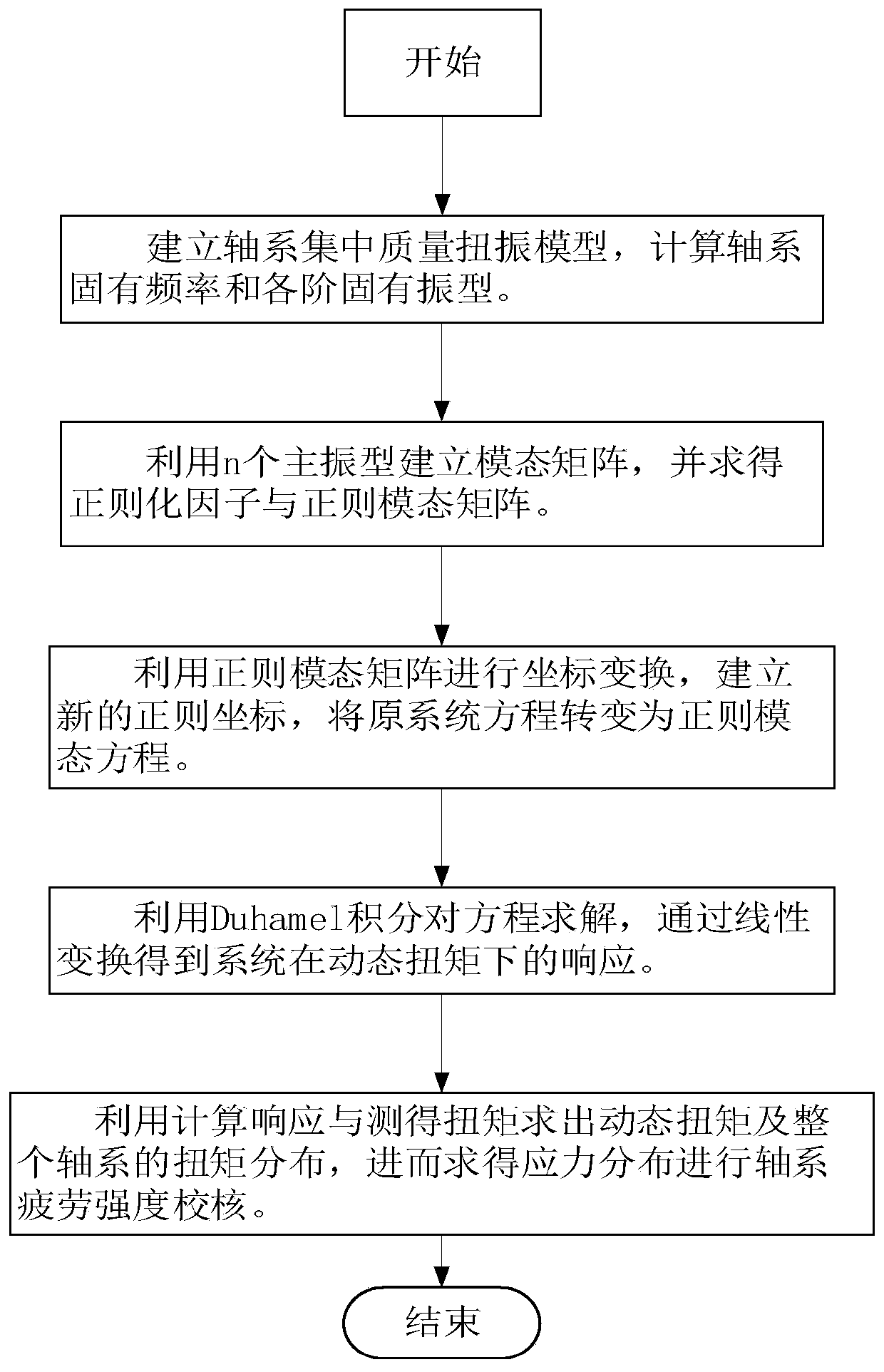
[0067] make Solve to obtain the natural frequency ω of shafting torsion n1 , ω n2 , ω n3 , ω n4 and various modes of vibration.

[0068] ...


PUM


Abstract

The invention discloses a rotary machinery shafting fatigue strength detection method which comprises the following steps of S1, establishing a concentrated mass torsional vibration model of a targetshafting to obtain a motion equation of the target shafting under the action of a dynamic torque T; s2, establishing a modal matrix Phi and calculating to obtain a regularization factor alpha so as toobtain a regularization modal matrix Phin; s3, converting the motion equation into a regular modal equation; s4, solving the responses and torque distribution of all shaft sections of the target shaft system; and S5, detecting the fatigue strength of the target shaft system. According to the present invention, the torque distribution of the whole shaft system can be calculated only by arranging one measuring point, so that the field test process is simpler and more efficient, and the test efficiency is improved. According to the invention, the position of the measuring point can be selected at any shaft section of a shaft system, the method has very strong application capability in specific engineering practice, and is beneficial to adapting to the complex conditions of an engineering site.

Description

technical field [0001] The invention relates to a shaft system of a rotating machine, in particular to a method for detecting the fatigue strength of a shaft system of a rotating machine. Background technique [0002] In thermal power plants, fans and water pumps are the main power-consuming equipment, which have huge energy-saving potential. In recent years, the rapid development of the power grid and the continuous advancement of energy conservation and environmental protection have put forward higher and higher requirements for the safety of power plant operation and power generation costs. The power plant must adjust the operation mode of auxiliary equipment to meet the needs of power production. Therefore, many power plants have adopted frequency conversion technology to carry out technological transformation on fans, pumps and other equipment, and achieved good results. [0003] After the frequency conversion transformation of many equipments, many faults such as mult...

Claims


Application Information

Patent Timeline
IPC IPC(8): G06F17/50
CPCG06F30/17G06F2119/06Y02T90/00
Inventor 王瑜祥杨建刚
Owner SOUTHEAST UNIV
Why Eureka
Try Eureka