Supercharge Your Innovation With Domain-Expert AI Agents!

High-precision rotary jacking tip

A high-precision, top-notch technology, applied in the direction of tailstock/top, turning equipment, tool holder accessories, etc., can solve problems such as the adverse effect of workpiece machining accuracy, small ejector pins, etc., to improve cooling effect, increase area, reduce effect of dosage

Active Publication Date: 2019-07-26
CHONGQING HONGGANG CNC MACHINE TOOL
View PDF8 Cites 0 Cited by
  • Summary
  • Abstract
  • Description
  • Claims
  • Application Information

AI Technical Summary

Problems solved by technology

[0003] However, in actual use of this thimble structure, it is found that the workpiece will generate more heat during the machining process, and the heat will be transferred from the contact with the workpiece to the thimble, causing the thimble to deform. Due to the small eccentricity of the eccentric hole, the thimble The taper is small, so this deformation will have an adverse effect on the machining accuracy of the workpiece

Method used


Image

  • High-precision rotary jacking tip
  • High-precision rotary jacking tip
  • High-precision rotary jacking tip

Examples


Embodiment 1

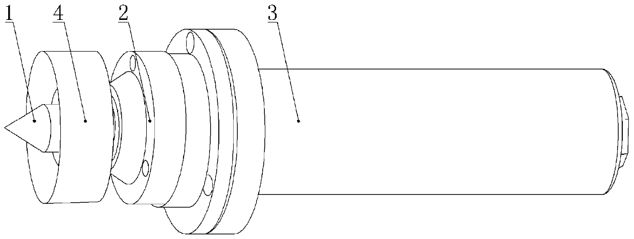
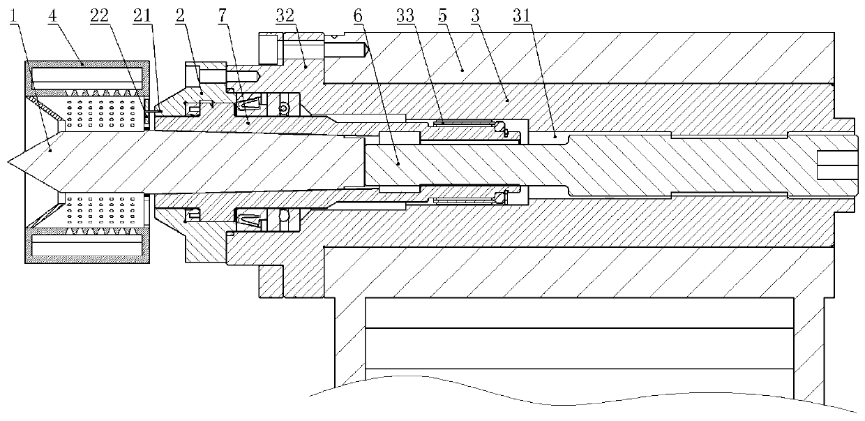
[0039] A high-precision rotating top, such as figure 1 and figure 2 As shown, including sleeve 3, mandrel 7, ejector rod 6, thimble 1 and protective cover 2, sleeve 3 is provided with installation hole, bearing hole and eccentric hole 31 in turn from left to right, installation hole, bearing hole and sleeve The barrel 3 is coaxial, and the eccentric hole 31 is set eccentrically relative to the sleeve 3 . The left end of the sleeve 3 is integrally formed with an annular connection plate 32, and several threaded holes are evenly distributed along the circumference of the connection plate 32. The sleeve 3 is inserted into the tailstock 5 of the machine tool. The right side wall of the connection plate 32 is connected to the left side of the tailstock 5. The walls are against each other, and the fixing of the sleeve 3 can be realized by screwing the bolts into the threaded holes and the tailstock 5 .

[0040] The mandrel 7 is installed in the mounting hole, the left end of the ...

Embodiment 2

[0053] On the basis of Example 1, such as Figure 5 , Figure 6 and Figure 7 As shown, the mandrel 7 of the present embodiment is provided with an annular waterproof groove 71 on the side wall away from the thimble 1. The waterproof groove 71 is located at the left end of the mandrel 7. The section of the waterproof groove 71 along the axial direction of the mandrel 7 is wedge-shaped. The protective cover 2 The bottom is provided with a first channel 23 communicating with the waterproof groove 71. When water mist enters the connection gap between the protective cover 2 and the mandrel 7, the water mist enters the waterproof groove 71 and is finally discharged through the first channel 23 to avoid water The fog erodes the bearing 33 . The bottom of the protective cover 2 is provided with a second channel 24 aligned with the waterproof groove 71. The second channel 24 is located on the left side of the first channel 23. A push rod 25 is slid in the second channel 24. The uppe...


PUM


Abstract

The invention relates to the field of numerical control machine tool components and parts and particularly discloses a high-precision rotary jacking tip. According to the high-precision rotary jackingtip, the side, away from a sleeve, of a protective cover is provided with a cooling tube, the cooling tube is arranged on the periphery of a jacking needle in a sleeving manner and can be driven to rotate by the jacking needle, the cooling tube is internally provided with an annular cooling cavity, the side wall, close to the jacking needle, of the cooling cavity is provided with a plurality of through holes, the cooling cavity is internally provided with a plurality of flow guide pieces in the circumferential direction, the flow guide pieces are fixed to the side wall, close to the jacking needle or away from the jacking needle, of the cooling cavity, and the side wall of the cooling cavity is provided with a lockable liquid inlet. By means of the scheme of the high-precision rotary jacking tip, the jacking tip can be cooled, and the jacking tip precision is improved.

Description

technical field [0001] The invention relates to the field of CNC machine tool parts, in particular to a high-precision rotating top. Background technique [0002] The top plays the role of positioning and supporting the workpiece during the machining process. During assembly, the top is assembled on the tailstock of the machine bed, and the tailstock can slide on the machine bed. However, the taper of the thimble in the center will change during use, which will reduce the precision of the produced parts, so it is necessary to adjust the taper. The traditional adjustment requires professionals for more than ten minutes or even longer. In order to improve the efficiency of adjustment , our company has developed a taper quick-adjustable thimble structure with application number 201611141381.0. This thimble structure includes thimble, sleeve, fixed pin, mandrel, ejector rod and protective cover, etc. The sleeve is provided with an eccentric hole, the ejector rod is threaded wit...

Claims


Application Information

Patent Timeline
Patent Type & Authority Applications(China)
IPC IPC(8): B23B23/04
CPCB23B23/045
Inventor 汪传宏
Owner CHONGQING HONGGANG CNC MACHINE TOOL
Features
  • R&D
  • Intellectual Property
  • Life Sciences
  • Materials
  • Tech Scout
  • Unparalleled Data Quality
  • Higher Quality Content
  • 60% Fewer Hallucinations
Learn More