Self-centering chuck

A self-centering chuck and chuck technology, which is applied in the direction of chucks, turning equipment, toolholder accessories, etc., can solve the problems of chucks being easy to get stuck in iron cutting, easy to wear jaws, shaking medium precision, etc., and it is not easy to achieve The effect of resistance, good sealing and low wear

Inactive Publication Date: 2019-07-26
杨晓林
View PDF10 Cites 13 Cited by
  • Summary
  • Abstract
  • Description
  • Claims
  • Application Information

AI Technical Summary

Problems solved by technology

[0003] The technical problem to be solved by the present invention is to provide a self-centering chuck for the problems that the existing automatic cente

Method used


Image

  • Self-centering chuck
  • Self-centering chuck
  • Self-centering chuck

Examples


Example Embodiment

[0022] The technical solutions in the embodiments of the present invention will be clearly and completely described below with reference to the accompanying drawings of the present invention. Obviously, the described embodiments are only a part of the embodiments of the present invention, rather than all the embodiments. Based on the embodiments of the present invention, all other embodiments obtained by those of ordinary skill in the art without creative work fall within the protection scope of the present invention. The words "up", "down", "left" and "right" appear in the following text, which only means that the directions of up, down, left and right are consistent with the drawings themselves, and do not limit the structure.
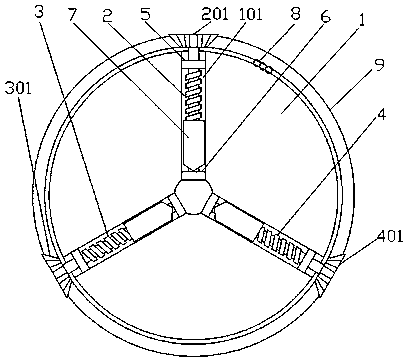
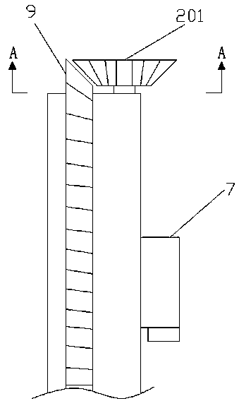
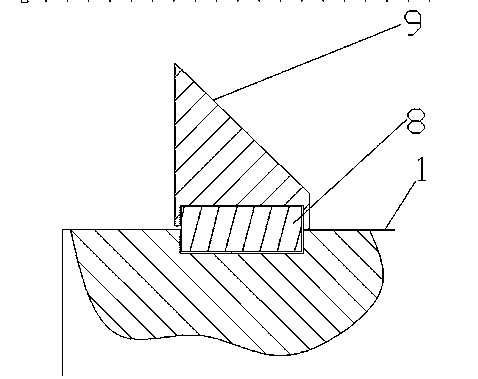
[0023] like Figures 1~5 The shown self-centering chuck includes a chuck main body 1 and a jaw 7; one end of the chuck main body 1 is equiangularly opened with three rectangular grooves 101 around the central axis, and the three grooves 101 are close...


PUM


Abstract

The invention discloses a self-centering chuck, and belongs to the field of machining clamps. According to the technical scheme, three grooves which are arranged at equal angles around the central axis are formed in the end surface of a chuck main body, and a guide rail lead screw is rotationally connected in each groove; each guide rail lead screw extends to the outer circle end of the chuck mainbody to be fixedly provided with a bevel gear, and the three bevel gears are meshed with annular bevel gears which are rotationally connected to the outer circle end of the chuck main body, so that when one guide rail lead screw rotates, the other two driven bevel gears are driven to rotate through the annular bevel gears, and then the corresponding guide rail lead screw is driven to rotate; dueto the fact that outer threads of the guide rail lead screws are meshed with threaded holes on the sleeved clamping jaws, so that the lead screws rotate to drive the clamping jaws to linearly move towards the center axis of the chuck main body, and thus the clamping effect is achieved; due to the fact that the lead screw mechanism is small in abrasion degree, the sealing performance is good, the clamping jaws move back and forth and are not prone to blockage, and compared with a traditional self-centering chuck, the transmission efficiency is higher, and positioning is more accurate.

Description

technical field [0001] The invention belongs to the field of machining fixtures, in particular to a self-centering chuck. Background technique [0002] The slewing ring is a large bearing capable of bearing comprehensive loads, and can simultaneously bear large axial and radial loads and overturning moments. The slewing bearing is widely used in the actual industry and is called "the joint of the machine". Essential important transmission components. With the rapid development of the machinery industry, slewing bearings have been widely used in marine equipment, engineering machinery, light industrial machinery, metallurgical machinery, medical machinery, industrial machinery and other industries. The slewing bearing needs to use fixtures for positioning during the machining process. The existing general fixtures mainly include vise, three-jaw chuck, four-jaw chuck and so on. Among them, the existing self-centering chucks are generally three-jaw chucks, but their clamping...

Claims


Application Information

Patent Timeline
IPC IPC(8): B23B31/169
CPCB23B31/16
Inventor 杨晓林
Owner 杨晓林
Why Eureka
Try Eureka