
3D printer and 3D printing method

A 3D printer and printing nozzle technology, applied in the field of 3D printing, can solve the problems of difficulty in mass production printing, differences, complicated operation, etc., and achieve the effect of enriching the 3D printing structure

Active Publication Date: 2019-07-26
REGENOVO BIOTECH
View PDF6 Cites 4 Cited by
  • Summary
  • Abstract
  • Description
  • Claims
  • Application Information

AI Technical Summary

Problems solved by technology

[0002] The existing 3D printing system is only suitable for printing single-piece mold samples. When mass production is required, after the printing of samples is completed, it is necessary to manually remove the samples on the printing table, and then control the operation of the printer. Due to the single-piece sample Printing takes a certain amount of time, so in the mass production process, people need to periodically remove the samples on the printing table, or make the 3D printing system move to other locations after printing the first sample through complex program settings The printing of the second sample leads to the following disadvantages of the existing 3D printing system, which is difficult to apply to mass production printing: (1) The operation is cumbersome, and manual assistance is required when printing samples in large quantities; (2) Printing of all samples After the completion, the post-processing and other operations are uniformly performed, resulting in different samples waiting for post-processing time after printing is completed, resulting in differences; (3) Different samples are printed at different locations, and the environmental factors during printing are slightly different, resulting in differences

Method used


Image

  • 3D printer and 3D printing method
  • 3D printer and 3D printing method
  • 3D printer and 3D printing method

Examples


Embodiment Construction

[0097] The terms "first", "second", "third" and so on are only used for distinguishing descriptions, and do not represent sequence numbers, nor can they be understood as indicating or implying relative importance.

[0098] Furthermore, the terms "horizontal", "vertical", "overhanging" and the like do not imply that the part is absolutely level or overhanging, but that tilts are allowed within a 10% tolerance. The orientation or positional relationship indicated by the terms "upper", "lower", "left", "right" and the like are based on the orientation or positional relationship shown in the drawings, rather than indicating or implying that the referred device or element must have a specific orientation, constructed and operated in a specific orientation.

[0099] In the description of this application, unless otherwise clearly stipulated and limited, the terms "installation", "installation", "connection" and "connection" should be understood in a broad sense, for example, it can ...


PUM


Abstract

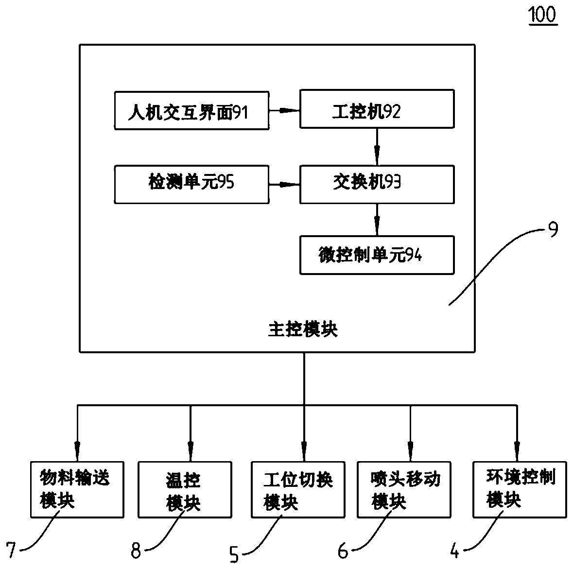
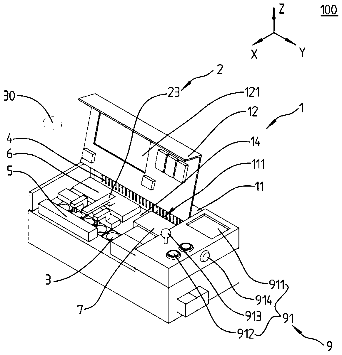
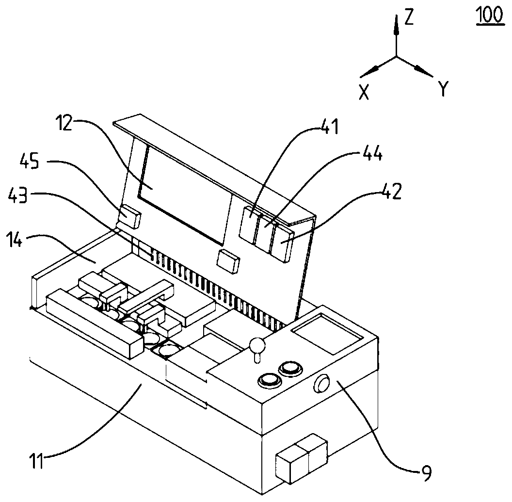
The invention discloses a 3D printer and a 3D printing method, and relates to the technical field of 3D printing. The 3D printer disclosed by the invention comprises a chassis, an environment controlmodule, a station switching module, a spray head movement module, a material conveying module, temperature control modules and a main control module, wherein a conveying spray head, a plurality of stations and a plurality of printing utensils are arranged in the chassis; the conveying spray head is arranged above the stations; the printing utensils are arranged on the stations; the conveying sprayhead comprises a printing spray head; the environment control module is arranged in the chassis; the station switching module is arranged in the chassis and is used for driving the printing utensilsto be transferred among the various stations; the spray head movement module is connected with the printing spray head and is used for driving the printing spray head to be transferred among the various stations; the material conveying module is connected with the conveying spray head and is used for conveying materials to the conveying spray head; and the temperature control modules are arrangedon the material conveying module, the stations and the printing spray head, and are used for regulating temperatures. The 3D printer disclosed by the invention is applied to batch production.

Description

technical field [0001] The present application relates to the technical field of 3D printing, in particular, to a 3D printer and a 3D printing method. Background technique [0002] The existing 3D printing system is only suitable for printing single-piece mold samples. When mass production is required, after the printing of samples is completed, it is necessary to manually remove the samples on the printing table, and then control the operation of the printer. Due to the single-piece sample Printing takes a certain amount of time, so in the mass production process, people need to periodically remove the samples on the printing table, or make the 3D printing system move to other locations after printing the first sample through complex program settings The printing of the second sample leads to the following shortcomings of the existing 3D printing system, which is difficult to apply to mass production printing: (1) The operation is cumbersome, and manual assistance is requir...

Claims


Application Information

Patent Timeline
Patent Type & Authority Applications(China)
IPC IPC(8): B29C64/135B29C64/20B29C64/209B29C64/232B29C64/236B29C64/245B29C64/255B29C64/314B29C64/321B29C64/393B33Y10/00B33Y30/00B33Y40/00B33Y50/02
CPCB29C64/135B29C64/20B29C64/209B29C64/232B29C64/236B29C64/245B29C64/255B29C64/314B29C64/321B29C64/393B33Y10/00B33Y30/00B33Y40/00B33Y50/02
Inventor 徐铭恩雷鑫槐王玲
Owner REGENOVO BIOTECH
Learn More