Automatic charging device, automatic charging device control method and display device

A technology of automatic charging device and equipment, which is applied in the directions of transportation and packaging, thin material handling, and conveying filamentous materials. Effect

Active Publication Date: 2021-01-22
BOE TECH GRP CO LTD
View PDF5 Cites 0 Cited by
  • Summary
  • Abstract
  • Description
  • Claims
  • Application Information

AI Technical Summary

Problems solved by technology

[0004] However, when the motor drives the reel to take in and out the wire, it is easy to cause the wire to be entangled and knotted, which will affect the use, especially when the automatic charging device is tilted or turned upside down, it is easy to cause the wire to be unwrapped and unwrapped. Case

Method used


Image

  • Automatic charging device, automatic charging device control method and display device
  • Automatic charging device, automatic charging device control method and display device
  • Automatic charging device, automatic charging device control method and display device

Examples


Embodiment 1

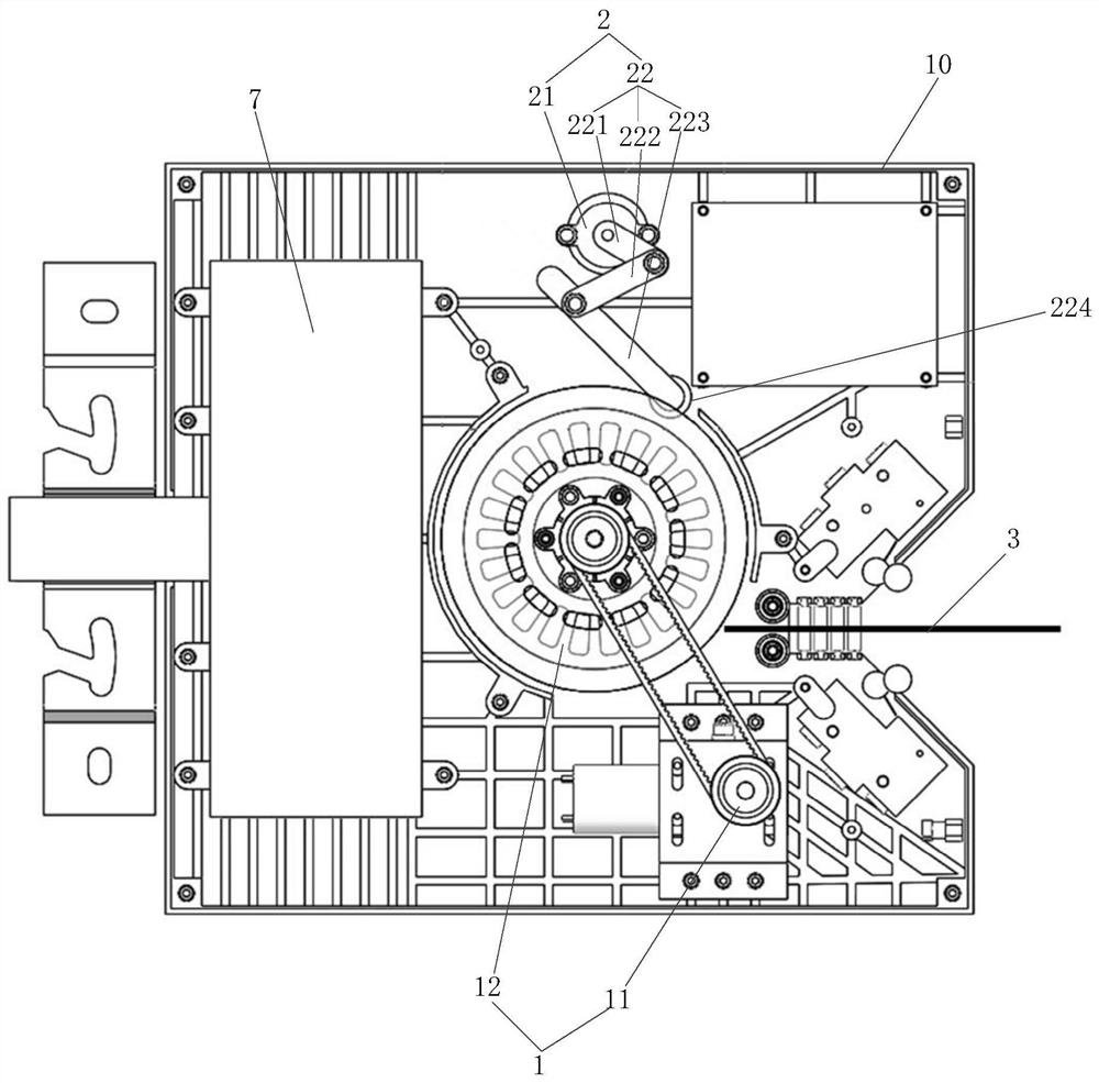
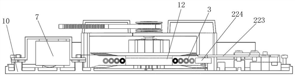
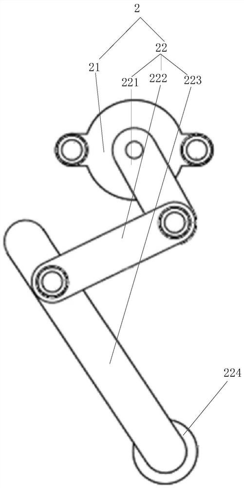
[0037] Such as Figure 1-3 As shown, the first embodiment of the present invention proposes an automatic charging device, which includes: a take-up and pay-off device 1, a limit device 2 and a controller 4, and the take-up and pay-off device 1 includes a first drive motor 11 and a reel 12. The first drive motor 11 drives the reel 12 to rotate reciprocally, and the reel 12 is used to wind the discharge connecting wire 3; the limit device 2 includes a second drive motor 21 and a pressing structure 22, the The second driving motor 21 drives the pressing structure 22 to press on the surface of the outermost circle of the electrical connection wire 3 wound by the reel 12; the controller 4 communicates with the first driving motor 11 and the second The two driving motors 21 are connected to control the reciprocating rotation of the first driving motor 11 to drive the reel 12, and to control the pressing force of the second driving motor 21 on the electrical connection wire 3 through...

Embodiment 2

[0057] An automatic charging device control method proposed in Embodiment 2 of the present invention is used for the above-mentioned automatic charging device, which includes: the controller controls the first driving motor and the second driving motor to rotate simultaneously, and controls the first driving motor to rotate clockwise Or every turn counterclockwise, the second drive motor is controlled to drive the holding structure to hold one end of the electrical connection wire, and approach or leave the axis of the reel at a distance equal to the diameter of the electrical connection wire.

[0058] Specifically, when the controller receives a charging signal, such as a charging signal from the battery management unit, the controller can control the first driving motor and the second driving motor to work simultaneously, and since the first driving motor controls the The electrical connection wire is wound around the reel, and the second drive motor controls the swing of the...

Embodiment 3

[0061] A display device proposed in Embodiment 3 of the present invention, which includes: an automatic charging device; Figure 1-Figure 3 As shown, the automatic charging device includes: a take-up and pay-off device 1, a limit device 2 and a controller 4, and the take-up and pay-off device 1 includes a first drive motor 11 and a reel 12, and the first drive motor 11 drives The spool 12 rotates reciprocatingly, and the spool 12 is used for winding the discharge connecting wire 3; the limiting device 2 includes a second driving motor 21 and a pressing structure 22, and the second driving motor 21 drives the pressing and holding The structure 22 is pressed on the surface of the outermost circle of the electrical connection wire 3 wound by the reel 12; the controller 4 is connected with the first drive motor 11 and the second drive motor 21 for controlling the The first driving motor 11 drives the reciprocating rotation of the reel 12, and controls the pressing force of the sec...


PUM


Abstract

A wire collection device, comprising: a wire winding and unwinding device (1), a limiting device (2) and a controller (4). The wire winding and unwinding device (1) comprises a first drive motor (11) and a reel (12), wherein the first drive motor (11) drives the reel (12) to reciprocate. The reel (12) is configured to wind up a winding and unwinding electrical connection wire (3) in use. The limiting device (2) comprises a second drive motor (21) and a pressing structure (22), wherein the second drive motor (21) is configured to drive the pressing structure (22) to press on the surface of the outermost circle of the electrical connection wire (3) wound by the reel (12) in use. The controller (4) is in signal connection with the first drive motor (11) and the second drive motor (21), and is configured to control the first drive motor (11) to drive the reel (12) to reciprocate, and to control the second drive motor (21) to apply a pressing force to the electrical connection wire (3) in use through the pressing structure (22). The wire collection device solves the problem of disordered winding of electrical connection wires. The present invention further relates to a charging device, a charging device control method, and an electronic device.

Description

technical field [0001] The invention relates to the technical field of charging, in particular to an automatic charging device, a control method of the automatic charging device and a display device. Background technique [0002] At present, many electronic devices are equipped with automatic charging devices, such as display devices such as picture screens. These display devices are all provided with rechargeable batteries, and are equipped with automatic charging devices that can automatically retract and unwind the wires and connectors for electrical connection. To realize the automatic charging of the rechargeable battery. [0003] In the existing automatic charging device, the retractable wire rod is retracted and retracted through the reel, and the wire rod is retracted and retracted by the reel under the drive of the driving motor. [0004] However, when the motor drives the reel to take in and out the wire, it is easy to cause the wire to be entangled and knotted, w...

Claims


Application Information

Patent Timeline
Patent Type & Authority Patents(China)
IPC IPC(8): B65H75/38B65H75/44B65H54/52
CPCB65H54/52B65H75/38B65H75/44B65H75/4405B65H2701/34
Inventor 邹祥祥穆东磊赵真许博妮张学博关红涛
Owner BOE TECH GRP CO LTD
Why Eureka
Try Eureka