Automatic pipe winder of winding type heat exchanger

A heat exchanger, winding technology, applied in the field of automatic tube winding machines, can solve the problems of low production efficiency, inability to meet the simultaneous winding of multiple heat transfer tubes, etc., and achieve the effects of easy layout, compact structure and good performance

Active Publication Date: 2016-02-03
杭州量创科技咨询有限公司
View PDF7 Cites 7 Cited by
  • Summary
  • Abstract
  • Description
  • Claims
  • Application Information

AI Technical Summary

Problems solved by technology

However, the problem with this tube winding machine is that the single tube releasing device is arranged on one side of the central cylinder, so that the tube winding machine can only realize the winding of a single heat transfer tube, which cannot meet the needs of simultaneous winding of multiple heat transfer tubes , lower production efficiency

Method used


Image

  • Automatic pipe winder of winding type heat exchanger
  • Automatic pipe winder of winding type heat exchanger
  • Automatic pipe winder of winding type heat exchanger

Examples


Embodiment 1

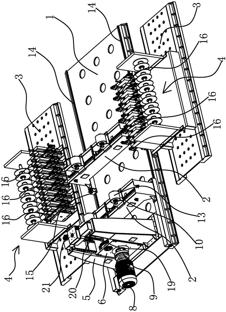
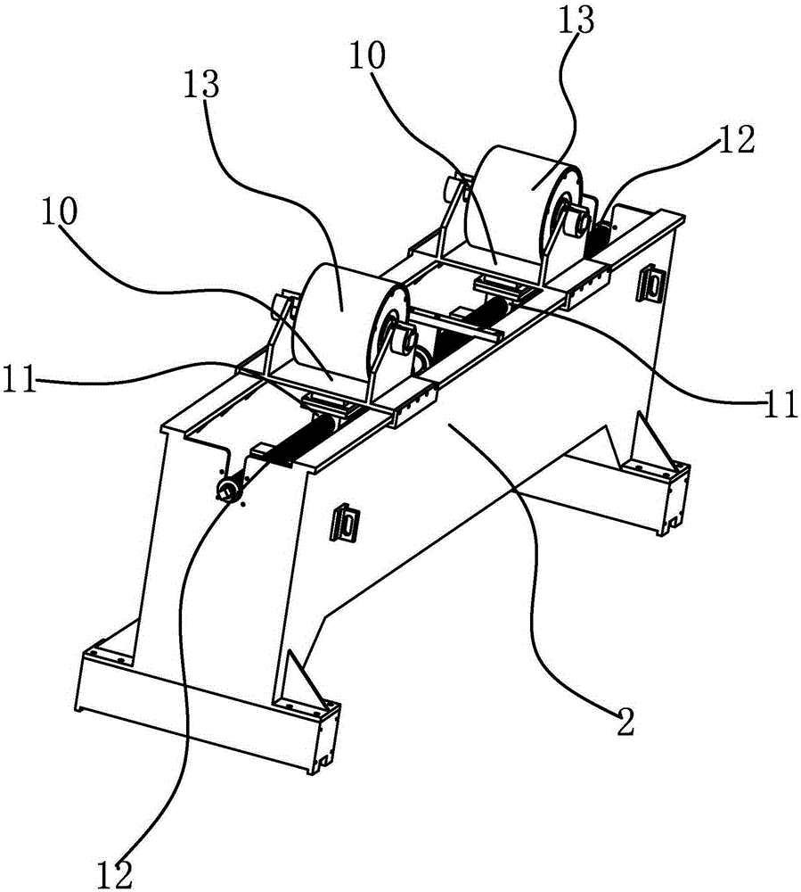
[0035] The automatic pipe winding machine of the winding heat exchanger includes a main guide rail bottom plate 1, a support seat 2, a feeding guide rail bottom plate 3, a self-correcting pipe feeding mechanism 4 and a traveling drive mechanism.

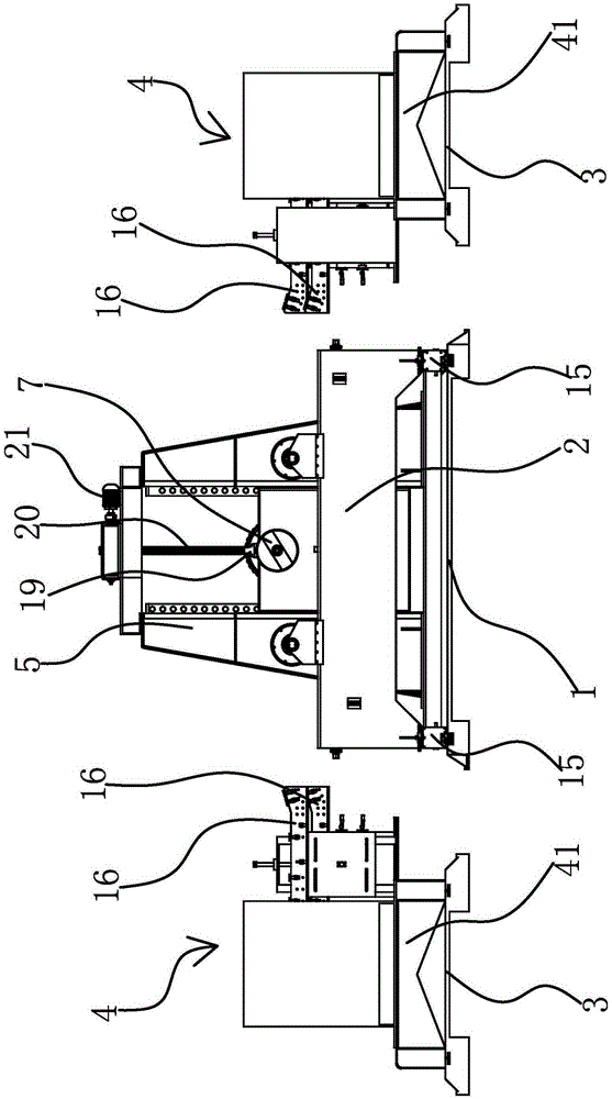
[0036] Specifically, as figure 1 and figure 2 As shown, a guide rail 14 is provided on the main rail bottom plate 1, and the two support seats 2 are slidably connected to the main rail bottom plate 1 along the length direction of the main rail bottom plate 1 through the guide rails 14, and a compression block is arranged between the support seat 2 and the guide rail 14. 15. Such as Figure 4 As shown, the pressing block 15 includes two oppositely arranged L-shaped pressing plates 151 and a top panel 152 at the top of the pressing plates 151. The bottom of the pressing plate 151 has an outstretched abutting portion 153 for abutting against The portion 153 can abut against the bottom surface of the guide rail 14 , and the top panel...

Embodiment 2

[0050] The technical solution in this embodiment is basically the same as that in the first embodiment, the difference is that in this embodiment, the support seat 2 is fixed on the main rail bottom plate 1 .

Embodiment 3

[0052] The technical solution in this embodiment is basically the same as the technical solution in Embodiment 1, the difference is that in this embodiment, the self-correcting tube feeding mechanism 4 includes a base 41 and a plurality of self-correcting tubes fixed on the base 41 The base 41 of the unit 16 is also provided with storage tanks 42 corresponding to the same number and positions of the self-correcting tube delivery unit 16 one-to-one.


PUM


Abstract

The invention provides an automatic pipe winder of a winding type heat exchanger and belongs to the technical field of machining equipment. The automatic pipe winder of the winding type heat exchanger solves the problem that an existing automatic pipe winder of the winding type heat exchanger is low in production efficiency. The automatic pipe winder of the winding type heat exchanger comprises a main guide rail bottom plate which is provided with at least two supporting bases in the length direction, and the supporting bases are used for supporting core tubes; the two sides of the main guide rail bottom plate are both provided with feeding guide rail bottom plates; each feeding guide rail bottom plate is provided with an automatic correcting pipe conveying mechanism; the automatic correcting pipe conveying mechanisms are located on the sides of the supporting bases and can be aligned with the core tubes located on the supporting bases; and the feeding guide rail bottom plates are further provided with travelling driving mechanisms capable of driving the automatic correcting pipe conveying mechanisms to slide along the feeding guide rail bottom plates. The automatic pipe winder of the winding type heat exchanger can wind a plurality of heat transfer pipes in a multi-layer manner.

Description

technical field [0001] The invention belongs to the technical field of mechanical processing equipment, and relates to an automatic pipe winding machine, in particular to an automatic pipe winding machine for a winding heat exchanger. Background technique [0002] The wound heat exchanger is formed by alternately winding the heat transfer tubes in the shape of a helix in the space between the core tube and the outer tube. The helical direction of the adjacent two layers of spiral heat transfer tubes is opposite, and a fixed shape Keep a certain distance from the parts. The winding heat exchanger has the advantages of compact structure, large heat transfer area per unit volume, simultaneous heat transfer of multiple media, and self-compensation of thermal expansion of the heat transfer tube. In actual production and processing, the heat transfer tube can be wound by a single tube, or two or more tubes can be wound together after welding. [0003] In order to realize the aut...

Claims


Application Information

Patent Timeline
Patent Type & Authority Applications(China)
IPC IPC(8): B21D53/06B21D11/06B21D43/08B21D3/05
Inventor 邓小雷夏鑫鑫杨震许天伟邱志伟徐宾
Owner 杭州量创科技咨询有限公司
Why Eureka
Try Eureka