Coil arrangement having two coils

A coil and linear technology, applied in the direction of coils, coil manufacturing, instruments, etc., can solve the problems of position sensors that are not suitable for precision purposes, small measurement accuracy, etc., and achieve high accuracy and improved measurement resolution.

Inactive Publication Date: 2015-09-09
ZF FRIEDRICHSHAFEN AG
View PDF13 Cites 6 Cited by
  • Summary
  • Abstract
  • Description
  • Claims
  • Application Information

AI Technical Summary

Problems solved by technology

[0006] It has proven that a position sensor constructed in this way is not very suitable for precise applications, since it has too small a measurement accuracy

Method used


Image

  • Coil arrangement having two coils
  • Coil arrangement having two coils
  • Coil arrangement having two coils

Examples


Embodiment Construction

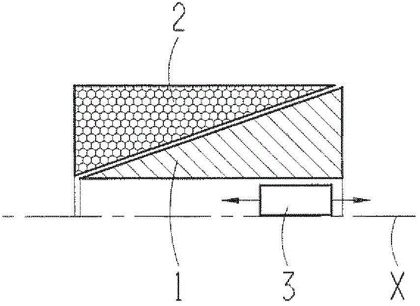
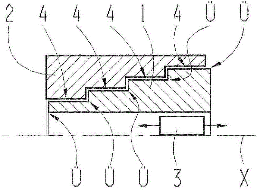
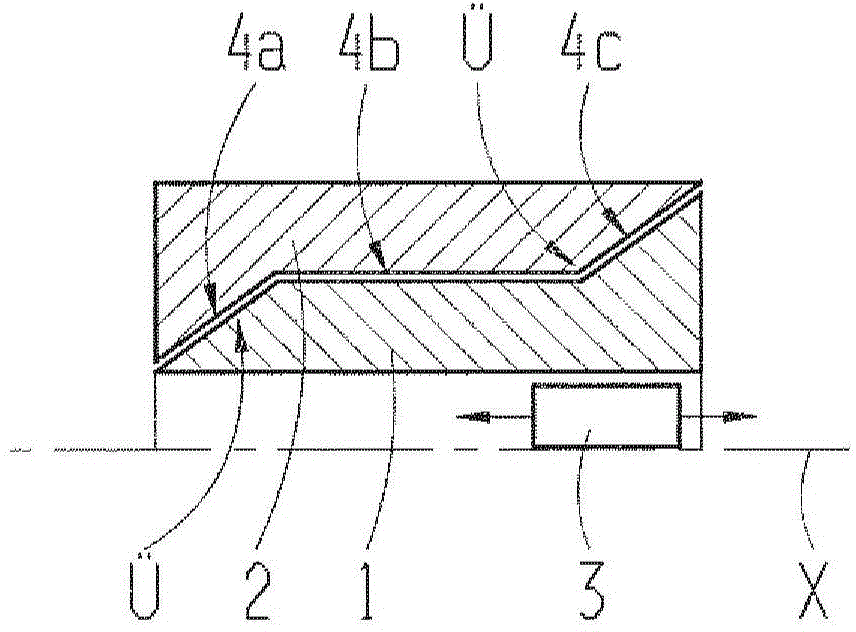
[0035] figure 1 , figure 2 and image 3 A coil system with a first coil 1 and a second coil 2 is shown in each case in longitudinal section along the coil longitudinal direction X. The lower half of the coils 1, 2 are not shown for the sake of clarity. The coil longitudinal direction X preferably simultaneously forms the axis of symmetry of the coil system. The coils 1 , 2 thus form a common hollow cylinder around the longitudinal direction X of the coils. The first coil 1 forms a radially inner coil, while the second coil 2 forms a radially outer coil. The coils 1 , 2 are thus arranged substantially coaxially staggered with respect to the coil longitudinal direction X. The individual windings of the coil 2 are shown as an example in the second coil 2 . The windings run orthogonally to the drawing plane of the drawing. As shown, the windings of the coils 1 , 2 are preferably arranged periodically next to each other in order to maximize the fill factor of the coils 1 , ...


PUM


Abstract

The invention relates to a coil arrangement, in particular for a position sensor, having a first coil (1) and a second coil (2) which are electrically connected to one another and are arranged in a substantially coaxial manner with respect to one another, wherein the first coil (1) has a winding density that increases in the longitudinal direction (X) of the coil arrangement, whereas the second coil (2) has a winding density which decreases in the longitudinal direction (X) of the coil arrangement. The invention also relates to a position sensor having such a coil arrangement and to a method for producing such a coil arrangement.

Description

technical field [0001] The invention relates to a coil system having a first coil and a second coil which are electrically connected to one another and arranged essentially coaxially to one another, wherein the first coil has an increasing winding density in the longitudinal direction of the coil system. Furthermore, the invention also relates to a position sensor and a method for producing the coil system. Background technique [0002] Various embodiments of contactless linear position sensors are known. The most important representation is sensing using a magnetic field. These are sensors using the Hall effect or the induction law. The latter in turn can be divided into two groups according to their principle of action. What both groups have in common is the system of coils and detection elements, which must be electrically conductive in the first group and soft magnetic in the second group. [0003] The first group (eddy current sensors) uses induction to build up a c...

Claims


Application Information

Patent Timeline
Patent Type & Authority Applications(China)
IPC IPC(8): G01D5/20
CPCG01D5/2013Y10T29/49073G01D5/2046H01F41/06H01F5/04
Inventor 亚历山大·格拉夫弗洛里安·魏因尔迈克尔·潘特克
Owner ZF FRIEDRICHSHAFEN AG
Why Eureka
Try Eureka