Stirring device for spray-blowing and stirring integrated molten iron desulphurization

A stirring device and a technology for desulfurization of molten iron, applied in the field of molten iron pretreatment, can solve the problems of low utilization rate of desulfurization agent, short treatment time, large temperature drop of molten iron, etc., improve the dynamic conditions of molten iron, and increase and decrease the cost of equipment investment. Effect of temperature drop loss

Pending Publication Date: 2019-07-26
WISDRI ENG & RES INC LTD
View PDF2 Cites 1 Cited by
  • Summary
  • Abstract
  • Description
  • Claims
  • Application Information

AI Technical Summary

Problems solved by technology

Mechanical agitation desulfurization and injection desulfurization are two main methods of molten iron desulfurization at present: the mechanical agitation desulfurization method is to immerse a stirring head lined with refractory material into the molten iron tank, and the driving device drives it to rotate, thereby stirring the molten iron and promoting the desulfurization of the molten iron. Desulfurization reaction occurs with desulfurizer to achieve the purpose of desulfurization of molten iron; this desulfurization method has good desulfurization effect, low production cost and short processing time, but the temperature drop of molten iron is large and the iron loss is large
The injection desulfurization method uses high-pressure gas as a carrier to spray the desulfurizer into the molten iron from the spray gun. The iron loss is small, but the dynamic conditions are poor, the desulfurizer and molten iron cannot fully react, the utilization rate of the desulfurizer is low, and the unit consumption cost of the desulfurizer is high

Method used


Image

  • Stirring device for spray-blowing and stirring integrated molten iron desulphurization
  • Stirring device for spray-blowing and stirring integrated molten iron desulphurization
  • Stirring device for spray-blowing and stirring integrated molten iron desulphurization

Examples


Embodiment Construction

[0021] In order to better understand the present invention, the present invention will be further described below in conjunction with the accompanying drawings and specific embodiments.

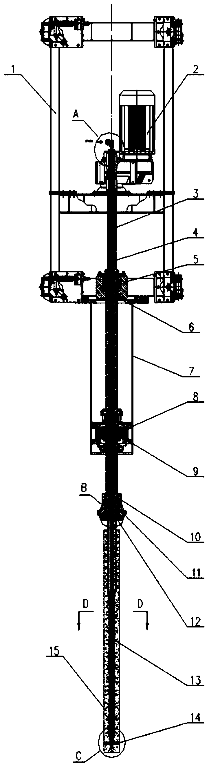
[0022] Such as figure 1 A stirring device for blowing and stirring composite molten iron desulfurization is shown, which includes a lifting frame 1, a rotary drive system, a transmission shaft 3, a stirring head and a powder air pipe. The lifting frame 1 is driven by a lifting drive system and can be vertically Lifting and locking; the rotary drive system is installed on the lifting frame 1, the drive end of the rotary drive system is connected to the transmission shaft 3; the transmission shaft 3 is vertically arranged, and the lower end of the transmission shaft 3 passes through the lower steel platform and is connected to the stirring head The powder gas pipe is located inside the transmission shaft 3 and the stirring head, and is arranged along the axial direction of the two; the inlet of...


PUM


Abstract

The invention discloses a stirring device for spray-blowing and stirring integrated molten iron desulphurization. The stirring device comprises a lifting framework, a rotary drive system, a transmission shaft, a stirring head and a powder gas tube, wherein the lifting framework is driven by a lifting drive system, and can ascend, descend and lock in a vertical direction; the rotary drive system ismounted on the lifting framework; the drive end of the rotary drive system is connected to the transmission shaft; the transmission shaft is perpendicularly arranged, and the lower end of the transmission shaft is connected to the stirring head; the powder gas tube is arranged inside the transmission shaft and the stirring head; an inlet of the powder gas tube communicates with a desulfurizing agent powder supply pipeline; and an outlet of the powder gas tube communicates with the outside. The stirring device has the beneficial effects that: spray-blowing desulphurization is taken as the basis, and a rotary drive device is introduced, so that a spray-blowing tube rotates and a gas stirring function is achieved, and therefore, the dynamic condition of molten iron is improved, the desulfurizing agent reacts with molten iron more sufficiently, and a utilization rate of the desulfurizing agent is increased.

Description

technical field [0001] The invention belongs to the technical field of molten iron pretreatment, and in particular relates to a stirring device for blowing and stirring composite molten iron desulfurization. Background technique [0002] With the development of society and the continuous improvement of steel quality requirements, hot metal desulfurization has become one of the indispensable links in steel production. Mechanical agitation desulfurization and injection desulfurization are two main methods of molten iron desulfurization at present: the mechanical agitation desulfurization method is to immerse a stirring head lined with refractory material into the molten iron tank, and the driving device drives it to rotate, thereby stirring the molten iron and promoting the desulfurization of the molten iron. Desulfurization reaction occurs with desulfurizer to achieve the purpose of desulfurization of molten iron; this desulfurization method has good desulfurization effect, l...

Claims


Application Information

Patent Timeline
Patent Type & Authority Applications(China)
IPC IPC(8): C21C1/02C21C7/064
CPCC21C1/02C21C7/064C21C7/0037
Inventor 严淑
Owner WISDRI ENG & RES INC LTD
Why Eureka
Try Eureka