Microwave irradiation pressurized sintering equipment and use method thereof

A pressure sintering and microwave irradiation technology, applied in the field of powder metallurgy, can solve the problems of reducing the mechanical and physical properties of materials, effectively reducing the sintering temperature, and uneven performance of sintered bodies, so as to achieve good industrial application prospects and shorten sintering process. The effect of low time and cost

Inactive Publication Date: 2010-07-28
WUHAN UNIV OF SCI & TECH
View PDF2 Cites 13 Cited by
  • Summary
  • Abstract
  • Description
  • Claims
  • Application Information

AI Technical Summary

Problems solved by technology

Different sintering technologies have their own characteristics, such as the "vacuum-hot-press sintering furnace" (CN1825041A) patented technology, although coaxial pressure is applied to the powder during the sintering process, the heating method of hot-press sintering is to Cavity heating, through thermal radiation and convective heat transfer, the powder material is heated up, the heating rate is slow, there is a temperature gradient in the material, the performance of the sintered body is uneven, the energy utilization rate is low, and the production cost is increased.
In addition, hot pressing sintering has no activation effect on the powder and cannot effectively reduce the sintering temperature
Microwave sintering is to heat up the powder material through microwave heating, such as the patented technology of "Microwave Sintering Equipment and Method" (CN101285654A). Although the "body heating" characteristic of microwave is used, the density of the sintered body is often low. Reaching about 95% of the theoretical density, there are a lot of pores in the material, which reduces the mechanical and physical properties of the material

Method used


Image

  • Microwave irradiation pressurized sintering equipment and use method thereof
  • Microwave irradiation pressurized sintering equipment and use method thereof
  • Microwave irradiation pressurized sintering equipment and use method thereof

Examples


Embodiment Construction

[0023] Below in conjunction with accompanying drawing and specific embodiment, the present invention is further described, not limitation to its protection scope:

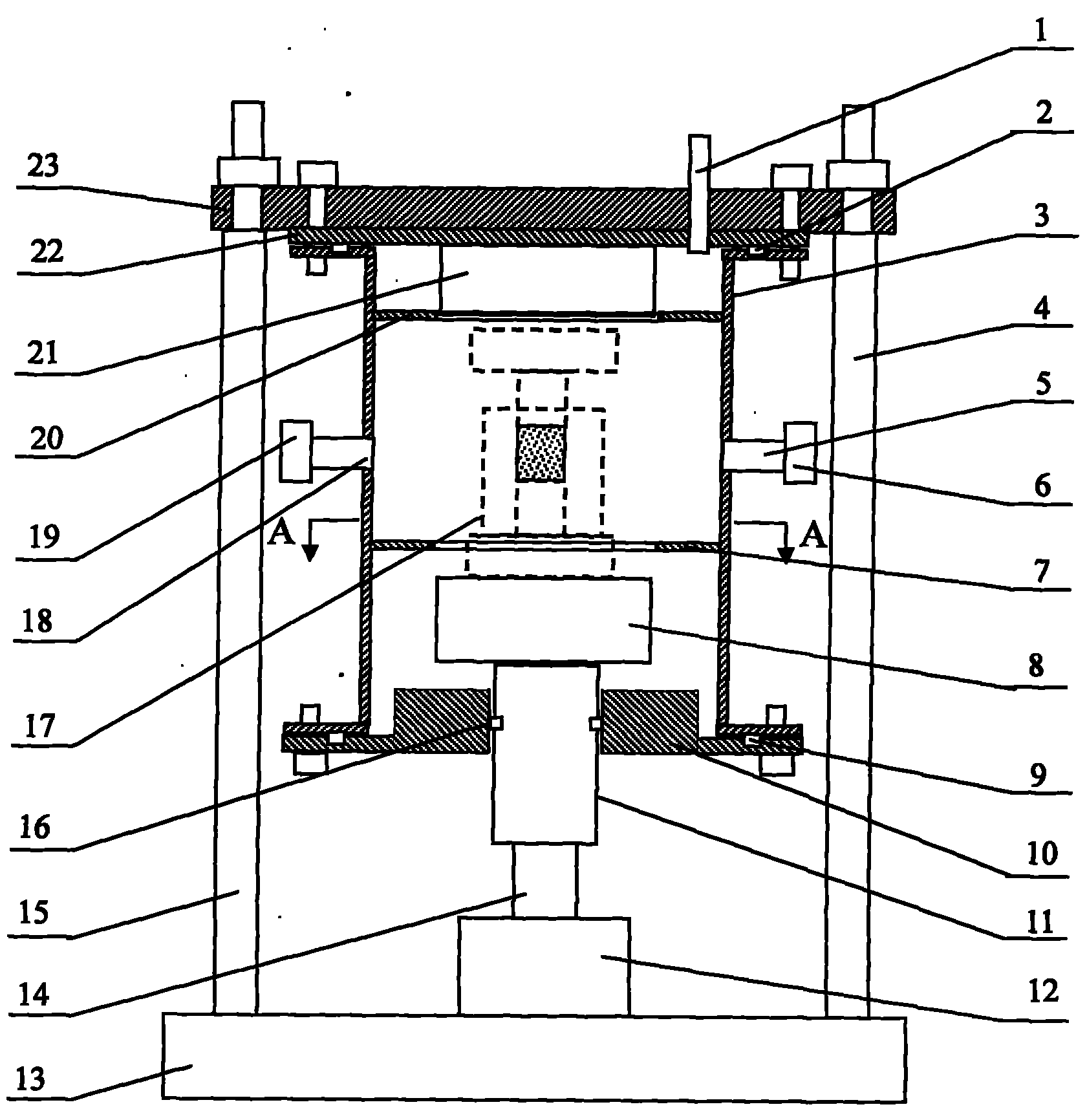
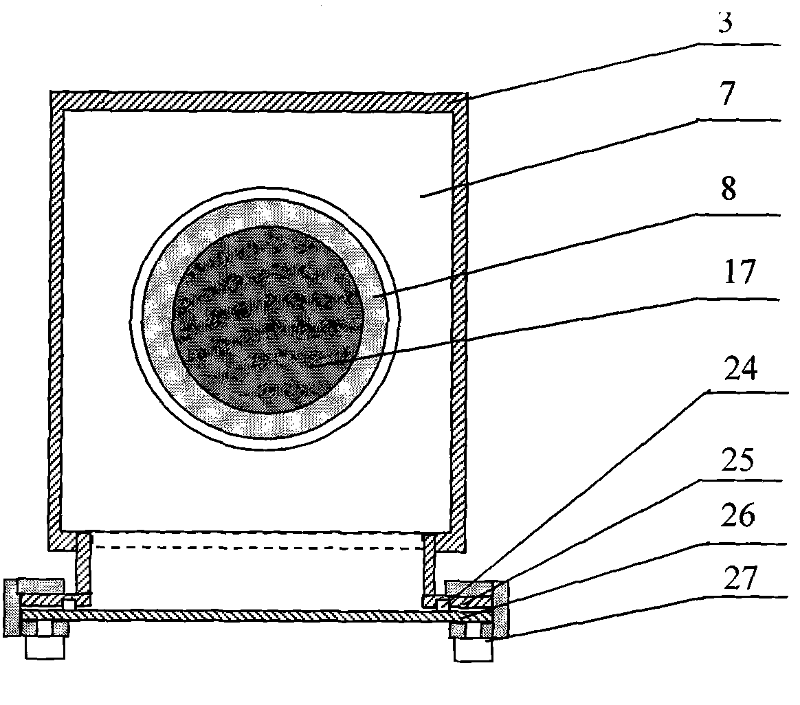
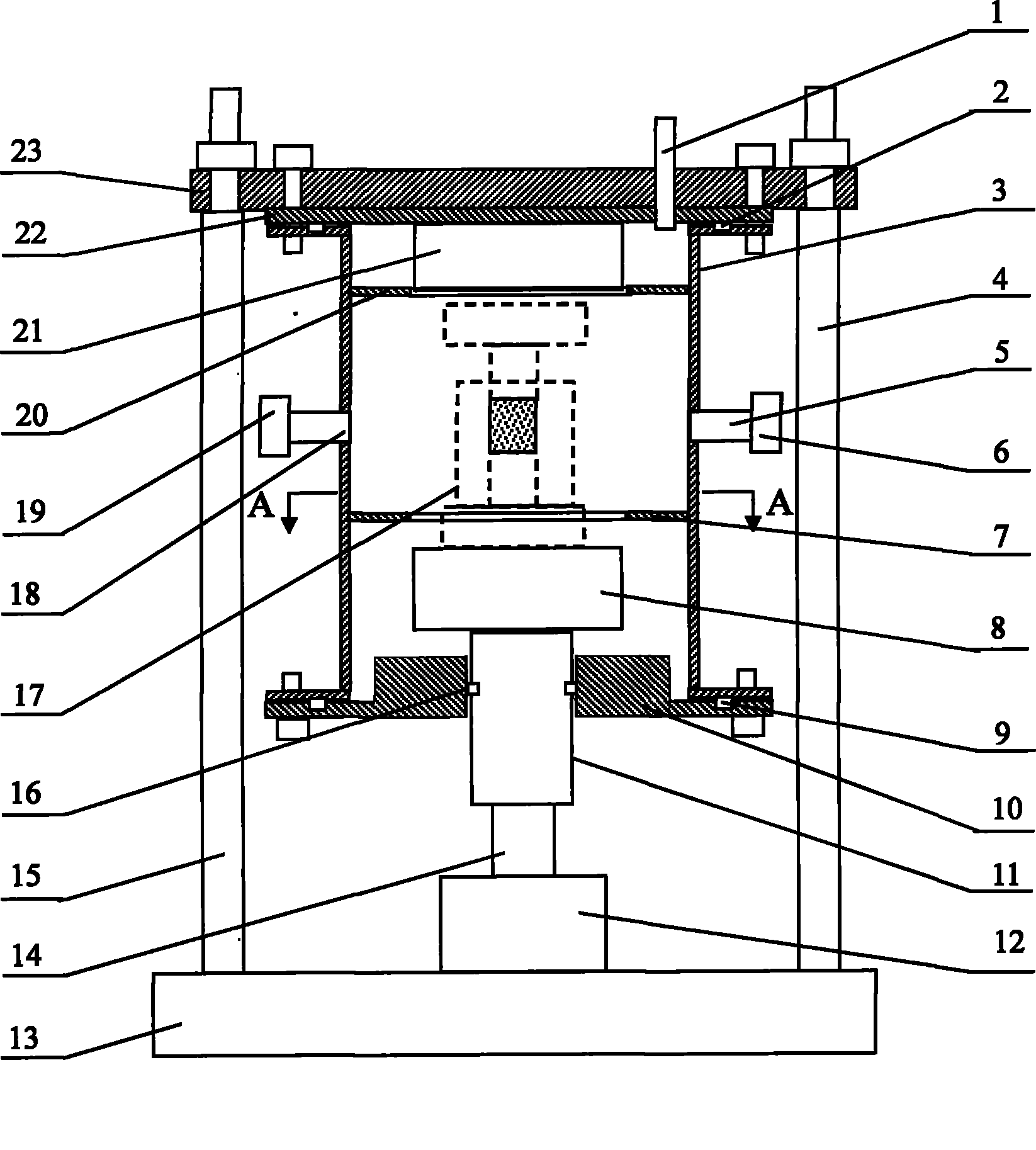
[0024] A microwave irradiation pressure sintering equipment and its use method, its structure is as follows figure 1 and figure 2 As shown: the lower ends of the two columns 4, 15 are respectively symmetrically fixed on the base 13, and the upper ends of the two columns 4, 15 are fixedly connected with the two ends of the beam 23; the upper cover 22 of the microwave oven is fixed on the lower plane of the beam 23, An upper pressure head 21 is fixedly installed at the center of the inner wall of the upper lid 22 of the microwave oven, and a microwave upper reflector 20 and a microwave lower reflector 7 are respectively fixed on the upper and lower parts of the inner wall of the side plate 3 of the microwave oven. The right side of the side plate 3 of the microwave oven is embedded with The first waveguide 5, the l...


PUM


Abstract

The invention relates to microwave irradiation pressurized sintering equipment and a use method thereof, which have the technical scheme that an upper pressing head (21) is fixedly arranged in the center of the inner wall of an upper oven cover (22) of a microwave oven, the upper part and the lower part of the inner wall of a side plate (3) of the microwave oven are respectively and fixedly provided with an upper microwave reflecting plate (20) and a lower microwave reflecting plate (7), a first waveguide tube (5) is embedded in the right side of the side plate (3) of the microwave oven, a second waveguide tube (18) is embedded in the left side of the side plate (3) of the microwave oven, the first waveguide tube (5) and the second waveguide tube (18) are respectively and fixedly connected with a first permatron (6) and a second permatron (19), a hydraulic cylinder (12) is vertically fixed in the center of a base (13), a slide block (11) passes through a chute hole of a lower oven cover (10), and a lower pressing head (8) is arranged on the upper part of the slide block (11). The invention has the characteristics that the sintering temperature can be effectively reduced, the sintering time can be shortened, microstructures of materials are convenient to control, crystal grains are thinned, the investment is saved, and the cost is low.

Description

technical field [0001] The invention belongs to the technical field of powder metallurgy. In particular, it relates to a microwave irradiation pressurized sintering device and a use method thereof. Background technique [0002] Sintering is a very important link in the production process of powder metallurgy. It is to heat the compact or loose powder to a temperature below its melting point (about 0.7 ~ 0.8T 理论熔点 ), so that molecules or atoms gain enough energy and migrate, causing bonding between powder particles, thereby obtaining a forming process of a highly dense structural material. Sintering has a decisive impact on the performance of powder metallurgy materials and products. By choosing different sintering methods and adjusting the sintering process parameters, the microstructure in the material can be effectively controlled, which ultimately determines the performance of the material. The development direction of sintering technology is low-temperature rapid sinte...

Claims


Application Information

Patent Timeline
Patent Type & Authority Applications(China)
IPC IPC(8): B22F3/14
Inventor 樊希安李光强宋新莉鲍思前朱诚意薛正良
Owner WUHAN UNIV OF SCI & TECH
Why Eureka
Try Eureka